Technical Manual & Parts Lists
22
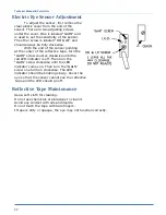
Electric Eye Sensor Adjustment
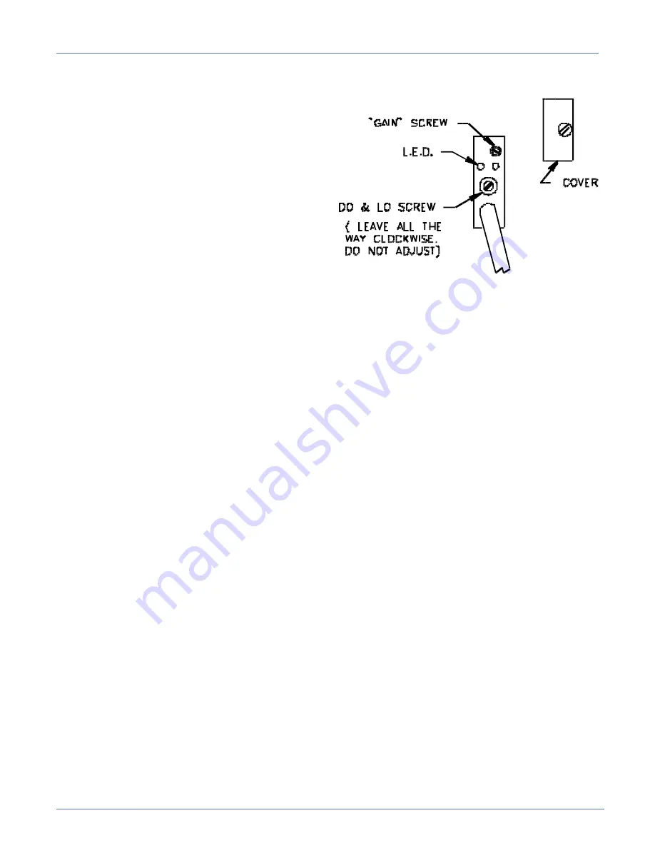
To adjust the sensor, first remove the
clear plastic cover from the end of the
sensor. There are two adjusting screws
under the cover. One is labeled “GAIN” and
is used to set the sensitivity of the sensor.
The other screw is labeled “DO & LO” and
should always be fully clockwise.
With the end of the sensor pointing
at the center of the reflective tape, turn the
“GAIN” screw counter-clockwise until the
red LED indicator is off. Then turn the
“GAIN” screw clockwise until the LED
indicator comes on. Then turn the “GAIN”
screw one full turn clockwise. The LED
indicator should be blinking slowly. Cover the
eye so that the sensor cannot see the reflective
tape and the LED should go off.
Reflective Tape Maintenance
Use a soft cloth for cleaning.
Do not use chemicals or abrasives to clean it.
Avoid any contact with oils and liquids.
Do not touch the tape with bare fingers.
If tape is dirty or opaque, the eye may not function correctly.
Summary of Contents for 1335MDS
Page 2: ......
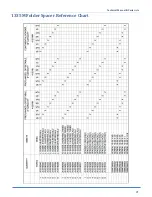
Page 27: ...Technical Manual Parts Lists 21 1335M Folder Spacer Reference Chart ...
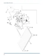
Page 30: ...Technical Manual Parts Lists 24 ...
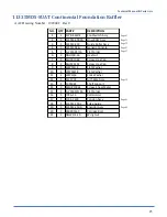
Page 32: ...Technical Manual Parts Lists 26 ...
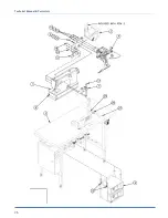
Page 34: ...Technical Manual Parts Lists 28 ...
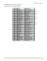
Page 36: ...Technical Manual Parts Lists 30 ...
Page 38: ...Technical Manual Parts Lists 32 ...
Page 40: ...Technical Manual Parts Lists 34 ...
Page 42: ...Technical Manual Parts Lists 36 ...
Page 44: ...Technical Manual Parts Lists 38 ...
Page 46: ...Technical Manual Parts Lists 40 ...
Page 48: ...Technical Manual Parts Lists 42 ...
Page 50: ...Technical Manual Parts Lists 44 ...
Page 52: ...Technical Manual Parts Lists 46 ...
Page 54: ...Technical Manual Parts Lists 48 ...
Page 56: ...Technical Manual Parts Lists 50 ...
Page 58: ...Technical Manual Parts Lists 52 ...
Page 60: ...Technical Manual Parts Lists 54 ...
Page 62: ...Technical Manual Parts Lists 56 ...
Page 66: ...Technical Manual Parts Lists 60 ...
Page 68: ...Technical Manual Parts Lists 62 ...
Page 70: ...Technical Manual Parts Lists 64 1335M 2400 Ball Screw and Nut Assembly 9000982 ...
Page 74: ...Technical Manual Parts Lists 68 ...
Page 76: ...Technical Manual Parts Lists 70 1335M PD Pneumatic Diagram 125618C ...
Page 77: ...Technical Manual Parts Lists 71 1335MDS PD Pneumatic Diagram 125670C ...
Page 78: ...Technical Manual Parts Lists 72 1335MDS WD Wiring Diagram 125650C ...
Page 79: ...Technical Manual Parts Lists 73 1335MDS WD1 Wiring Diagram 125573B ...
Page 80: ...Technical Manual Parts Lists 74 1335MDS WD2 Connection Diagram 125576B ...


