


Flexdeburr Installation and Operation Manual
Document: 9610-50-1007-11
Pinnacle Park
•
1031 Goodworth Drive
•
Apex, NC 27539
•
Tel: 919.772.0115
•
Fax: 919.772.8259
•
www.ati-ia.com
•
Email: [email protected]
21
Be aware of rotating parts. Use eye-protection while working around the deburring tool.
Be aware of high sound levels. While the Flexdeburr air motor is not loud, the cutting action
associated with deburring frequently is. Always use hearing protection while working in the
neighborhood of the deburring cell.
4.3 Operational
Considerations
For instructions on how to replace the burr, please consult Section 5.1.
In many robotic deburring applications, including steel and aluminum, no cooling or lubrication
of the rotary burr is necessary. For some materials and situations, the addition of coolants or
compressed air may aid the cutting process. If it is determined that liquid coolants are required,
a non-oil, cutting type should be used to prevent premature wear of the spindle bearing.
Burr selection is discussed in Section 4.5.
4.4 Tool Center Point (TCP) Position and Programming
Figure 2.1 shows the RC deburring tool dimensions. The Flexdeburr provides radial compliance
and performs best when the cuts taken are not excessively deep. The deburring tool spindle
must never be running while programming the robot. During teaching, the compliance air must
be on and supplied above a minimum of 0.35 bar [5 psi].
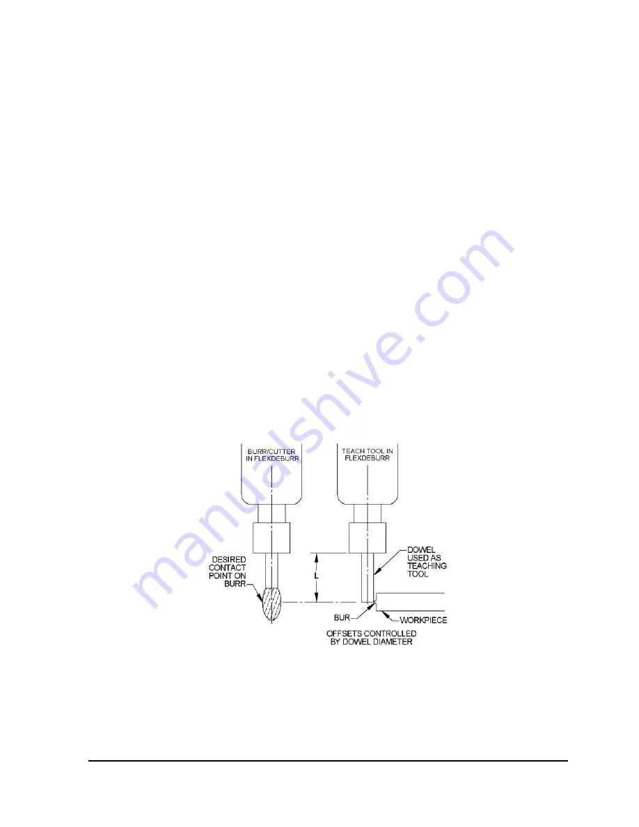
Two programming methods are suggested, but others are possible. In the first method, a dowel
pin of suitable diameter is inserted in place of a cutting tool (simulating the cutter shank
diameter) when teaching the robot path. For 6mm collets, this will mean a 6mm diameter pin of
suitable length. The dowel pin should extend sufficiently from the collet to reach the surface on
the burr where cutting is desired (see Figure 4.1). The diameter of the cutter should not exceed
that of the dowel pin by more than the compliance of the RC deburring tool.
Another programming method is to teach the path using the centerline of the burr as a guide,
following the edge of the part, and then manually or automatically adding offsets to the robot
path points to achieve the final correct burr path (see Figure 4.2). The programming method
used will depend on the robot’s capabilities and programmer preferences.
Figure 4.1—Flexdeburr Dowel Teaching Tool