background image

15

Button Wiring Management

NOTE:

 In this step, we feed the button wiring into 

the lower compartment. This is just one option and 
this step is optional as you may mount the button 
in any location you choose.

Based on where you want to place the switch 
button, you may want to run the wiring through 
the cabinet. If you want to run the button wiring 
through the cabinet, complete the steps that 
follow.

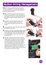
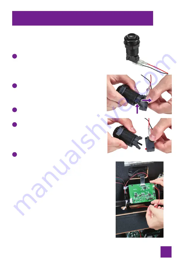
7KHEXWWRQZRQȇWȴWWKURXJKWKHKROHLQWKH

backbox to the main body, so we need to 
temporarily remove the top portion of the 
button.

Pull up on the arm lock carefully and slide out the 
microswitch to the right.

Feed the microswitch and wiring through the hole 
in the bottom of the backbox down below to the 
main pinball body. Then, you can feed the wires 
forward through the body to the front of the 
pinball machine.

It is your choice where you want to mount the 
switch button. One idea is to feed it to the front 
of the machine, reattach the button, and then 
drill a hole through the bottom of the cabinet. 
Then, the player can reach under the table and 
click on the switch button when needed. Of 
course, you can also leave it all in the back of the 
pinball machine if you desire. Reconnect the 
button to the microswitch when you have placed 
the wiring in your desired location.

A

B

C

D

E

Summary of Contents for LEGENDS PINBALL

Page 1: ...V I D E O I N P U T B A C K G L A S S S W I T C H B O A R D INSTRUCTION MANUAL...

Page 2: ......

Page 3: ...9 Later Production Installation P10 12 Connect Backglass EDP cable to VIBS EDP Port D P13 Connect Backglass EDP cable from mainboard to VIBS EDP Port A P14 Button Wiring Management P15 Attaching Backg...

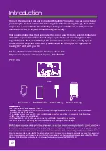
Page 4: ...Pinball machine VIBS for the AtGames Legends Pinball USB A USB A 2 0 or 3 0 cable used to connect your PC to the Legends Pinball machine Legends Pinball OCP is expecting two HDMI cables as input for...

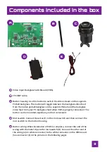
Page 5: ...feed from your PC backglass feed when VIBS is properly connected This EXWWRQ FDQ EH PRXQWHG DQ ZKHUH RX QG FRQYHQLHQW Microswitch Connect the wires E to this microswitch and then connect the microswi...

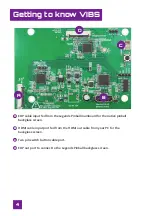
Page 6: ...board for the native pinball backglass screen HDMI cable input port fed from the HDMI out cable from your PC for the backglass screen Two pin switch button cable port EDP out port to connect to the Le...

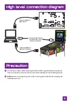
Page 7: ...ALP USB port USE OTG for controls Precaution Use extreme caution when handling the VIBS and the Legends Pinball components These are sensitive electronic devices and can be damaged if not handled prop...

Page 8: ...ositioned in an upright position You should only try to insert or remove the EDP cable when the port is in the unlocked position A The locked position is designated by the black bar SRVLWLRQHG LQ D DW...

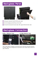
Page 9: ...s connections based on when your Legends Pinball was produced Reference the images above to determine if your model is Early Production or Later Production Remove backglass panel with key and set asid...

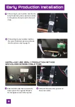
Page 10: ...t steps A If the wiring in your backbox matches the Later Production picture and looks like this picture skip to page 10 B INSTALLING VIBS EARLY PRODUCTION METHOD BACKGLASS SCREEN CABLE FEED Note the...

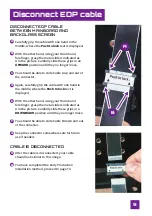
Page 11: ...the middle where the Push to lock text is displayed With the other hand using your thumb and IRUH QJHU JUDVS WKH PHWDO VOLGHUV LQGLFDWHG DV A in the picture Carefully slide these grips in a DOWNWARD p...

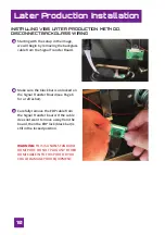
Page 12: ...r Board A Make sure the black bar is unlocked on the Signal Transfer Board see Page 6 for a refresher B Carefully remove the EDP cable from the Signal Transfer board If the cable does not want to move...

Page 13: ...s cable to the Signal Transfer Board Ensure the EDP connector on the signal transfer board is unlocked black bar raised A Carefully place the EDP cable BLUE end up into the EDP port on the green Signa...

Page 14: ...Slowly lower the feed cable and the Signal Transfer board into the compartment below until a few inches of the EDP cable remains in the backbox This completes the Later Production Method Continue wit...

Page 15: ...he VIBS board Unlock Port D on the VIBS board Carefully slide the EDP cable from the backbox into the Port D EDP slot making sure the cable lines up properly and does not meet resistance Do not crimp...

Page 16: ...VIBS board Carefully slide the EDP cable from the mainboard into the Port A EDP slot making sure the cable lines up properly and does not meet resistance Do not crimp or bend the EDP cable Once the c...

Page 17: ...n the arm lock carefully and slide out the microswitch to the right Feed the microswitch and wiring through the hole in the bottom of the backbox down below to the main pinball body Then you can feed...

Page 18: ...DMI in Port B Carefully push the wire into the connector until it is seated properly In our example we then fed the end of the HDMI cable into the lower body Then we connected the HDMI cable from the...

Page 19: ...DQ WKRVH SLFWXUHG Backglass video stream from PC variable interface e g HDMI Thunderbolt DisplayPort etc connects to VIBS board standard HDMI input port 0DLQ SLQEDOO SOD HOG VWUHDP IURP 3 YDULDEOH LQW...

Page 20: ...hine navigate to the Settings menu and click on the HDMI In icon You will see the screen in the image Set Control Mode to OTG Set Display to Main Display Set Degree to 90 Select the OK button You shou...

Page 21: ...glass monitor is not getting a signal This could be due to Your PC HDMI cable for the backglass video is not plugged into your computer or is not properly connected to the VIBS The EDP out cable from...

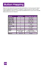
Page 22: ...OV RX PD PDS WKH SLQEDOO IXQFWLRQV DV RX VHH W WKH WDEOH below presents one set of options Control Button ID Pinball Application Option Left Flipper 11 Left Flipper Left Nudge 5 Left Nudge Right Flipp...

Page 23: ...BS or the Legends Pinball is damaged by the user in any way for any reason the user is responsible for the cost of replacement parts and any associated fees including shipping Note Standard warranty s...

Page 24: ...try to correct the interference by one or more of the following measures Reorient or relocate the receiving antenna Increase the separation between the equipment and receiver RQQHFW WKH HTXLSPHQW LQW...

Page 25: ...Interactive www atgames net PO Box 1691 El Segundo CA 90245 All rights reserved Content and images are for reference only and subject to change Made in China For additional support please email suppor...

Reviews: