background image

21

5.3 Add EnerLog to the server

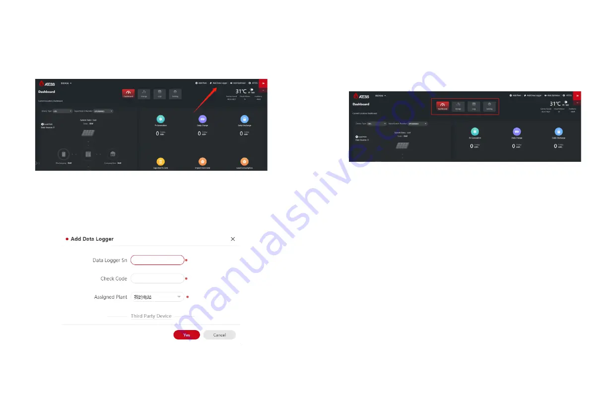
(1) After entering the main page of the server, click "Add Collector" in the upper right 
corner and follow the prompts to add EnerLog.     

(2)  Please  find  the  "collector  serial  number"  and  "collector  verification  code"  on  the 
EnerLog outer box or EnerLog shell.       

(3) For "Belonging to Power Plant", please select the corresponding power plant.       

5.4 View monitoring data

(1) After successfully adding EnerLog, return to the main page to view the monitoring 
information.      

(2) There are four page selection buttons on the main page, corresponding to different 
pages.      

Dashboard:

 The home page is the "Dashboard" page. Dashboard page display 

content: equipment real-time accumulated power, power, power and other information, 
as well as equipment energy trend graphs, battery information, monitoring equipment 
status and other information.

Energy: 

The energy page can view the data curve of each monitoring device, 

including voltage, current, power, battery SOC and other information. And the 
management of the power station.

Log: 

The log page can view the historical fault information of all devices.

Settings:

 Account setting functions, including account password modification, 

personal information modification and other functions.
 

You can view and monitor real-time data or historical data on the dashboard page or 
energy page.

20

Summary of Contents for EnerLog

Page 1: ...EnerLog User Manual SHENZHEN ATESS POWER TECHNOLOGY CO LTD www atesspower com 1st Floor of Building 3 at Sector B and 3rd Floor of Building 9 Henglong Industrial Park Shuitian Baoan District Shenzhen...

Page 2: ...nnect to device Installation and Connection CONTENT EnerLog internal page parameter setting 2 1 Device overview 2 2 Packing info 2 3 Function introduction Product description 1 2 3 4 4 1 IP access met...

Page 3: ...n a place that is convenient for installation operation and maintenance personnel ATESS will not notify users of any changes to this manual The contents of the manual will be continuously updated and...

Page 4: ...ace 2 Backup power input port see 3 2 1 for details Card slot Flow card socket not yet this function Reset Reset button Long press for 4 seconds to restart EnerLog long press for 10 seconds to restore...

Page 5: ...ormal operation RS485 3 LED Monitoring device data indicator the number of periodic flashing represents the number of devices communicating normally with the RS485 3 channel and EnerLog RS485 2 LED Mo...

Page 6: ...and viewing please refer to section 4 4 EnerLog monitors the devices through RS485 6 2 3 Function Introduction Installation and Connection 3 3 1 Installation environment EnerLog installation environme...

Page 7: ...10 devices The functions of the A1B1 A2B2 and A3B3 channels are the same 3 Other 485 communication equipment such as BMS combiner box etc the connection method is the same as that of the inverter 4 No...

Page 8: ...nal EnerLog page you need to search for the IP address through the router backend to log in 4 1 1 Dynamic IP login 1 Connect the PC and EnerLog to the same router so that they are in the same LAN 2 Fi...

Page 9: ...monitors the device you need to enter the internal page Add Device to add the device 4 4 1 Add device 1 Select the type of device in the first drop down list of Add or Remove Device for example select...

Page 10: ...mplete the deletion of the device 5 After saving successfully enter the device device status page to confirm whether the device is deleted successfully Notice 1 When deleting a device the options shou...

Page 11: ...ned from the router 3 If you need to set EnerLog to a static IP during use you need to make the following settings 1 Modify the enable to 0 turn off the DHCP function and modify it to a static IP 2 Se...

Page 12: ...nd password to log in to the server 2 When there are multiple power stations under this account in order to avoid confusion you need to create a new power plant before adding EnerLog 3 Click Add Power...

Page 13: ...rent pages Dashboard The home page is the Dashboard page Dashboard page display content equipment real time accumulated power power power and other information as well as equipment energy trend graphs...

Page 14: ...voltaic devices 3 On the Device Status page of the internal page check whether the device s communication address is consistent with the added device 4 Check whether the serial number of the monitored...

Page 15: ...0 devices RS485 communication distance Maximum 500 meters use shielded wire shielding layer grounded SHENZHEN ATESS POWER TECHNOLOGY CO LTD www atesspower com 1st Floor of Building 3 at Sector B and 3...

Reviews: