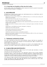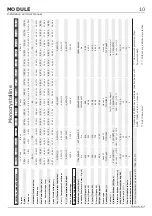
Installation
5.1.3.- Guide Instertion
5.2.1.-
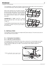
The proper torque values should be between 16 to 19Nm.
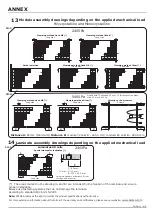
The placement of the dead end clamp (Hook clamp or another type), will be always at
the distance B (except for ½ 6
”
4x9 format modules, where the distance must be C),as
shown in the image of the annex (11-12). Minimum 4 dead end clamps per module
must be situated.
Assembly drawings depending on the applied load are displayed in annex.(View images
13-14)
Appropriate cable sections must be used to prevent voltage drops, which could cause a
drop in the power of the installation. As a rule, voltage drops in excess of 1,5% must
not be allowed.
(*)Check table of intensities max. of manufacturer's cable and the applicable
regulations.
5.2.- Electrical Installation
CABLE SECTION (Copper section):
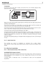
Put the first two fixing sets in place, and ensure they are vertically aligned. Fully
tighten the Allen screw (6).
Attach the other two fixing sets, aligning them vertically and move them along the rail
until they reach the panel.
Check that the modules are horizontally and vertically aligned and fully tighten the
screws to ensure the modules are firmly fixed to the guide rail.
The final fixing sets should be attached in the same way as the first two but in reverse.
Take a module that is already in place and then attach the set of fixings.
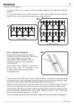
The modules are ready for installation by inserting into a guide system.
After insertion into the guide rails, panels must be fixed to prevent free sliding on the
guides.
Electrical Connection of the Juntion Box
6
20
mm
-1.5
+1.5
5
MODULE
Installation and User Manual
EN-MU-41 (4)-E


