background image

CS18208 / CS18216 User Manual

26

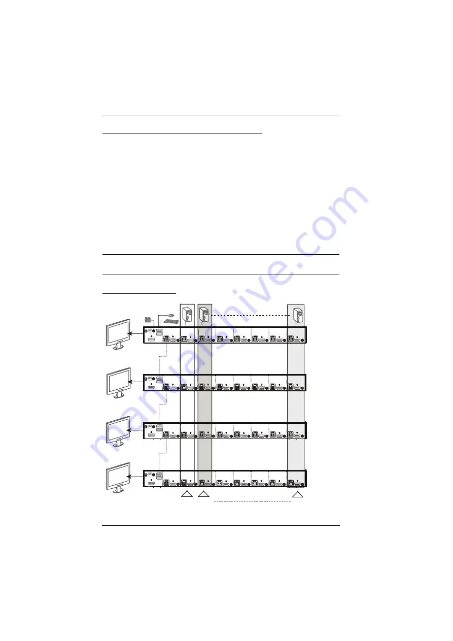
Grouping Ports into “Vertical” Channels

Once the cables have been connected and multi-display mode has been selected 
in the OSD, the CS18208 / CS18216 auto-detects the channels and displaying 
modes.Users can then assign them a channel number as the port name (the 
channels are represented by the vertical columns in the diagram below). So, all 
the Port 1s become Channel 1, all the Port 2s become Channel 2, ... , and all the 
Port 7s become Channel 7. The ports will all be switched at the same time, 
channel by channel.

Depending on the number of stages in your stack, a CS18208 / CS18216 
installation offers dual display (two stages), triple display (three stages), quad 

display (four stages) or multi-display (up to 8 stages) scenarios. For reference 
purposes, the example shows a four-stage installation with quad display 
functionality.

Note:

Only one HDMI video signal can be displayed at a time, depending on 

the configuration of the CS18208 / CS18216 unit on the first switch.

Channels Diagram

Ch1

Ch7 Ch6

First
Switch

Second
Switch

Third
Switch

Fourth
Switch

Summary of Contents for CS18208

Page 1: ...8 16 Port USB 3 0 4K HDMI KVM Switch CS18208 CS18216 User Manual www aten com CS18208 CS18216 8 16 Port USB 3 0 4K HDMI KVM Switch User Manual...

Page 2: ...Operation is subject to the following two conditions 1 this device may not cause harmful interference and 2 this device must accept any interference received including interference that may cause unde...

Page 3: ...prove defective following their purchase the buyer and not the manufacturer its distributor or its dealer assumes the entire cost of all necessary servicing repair and any incidental or consequential...

Page 4: ...to make sure that all the components are present and that nothing got damaged in shipping If you encounter a problem contact your dealer Read this manual thoroughly and follow the installation and op...

Page 5: ...ents 6 Front View CS18208 6 Front View CS18216 6 Rear View CS18208 9 Rear View CS18216 9 2 Hardware Setup Overview 11 Installation Types 11 Before You Begin 11 Stacking and Rack Mounting 12 Stacking 1...

Page 6: ...Number 31 OSD Login 31 OSD Hotkey 32 OSD Main Screen 32 OSD Main Screen Headings 33 OSD Navigation 33 OSD Functions 34 F1 Go To 35 F2 List 36 F3 Set 37 F4 Admin 39 F5 SKP 43 F6 BRC 44 F7 SCAN 45 F8 Lo...

Page 7: ...5 Logout 66 Open Close RS 232 Link 67 Set Baud Rate 68 Switch Port 69 Hotkey Setting 70 OSD Hotkey 71 USB Reset 72 Restore Default Settings 73 Firmware Upgrade 74 KVM Status 75 EDID Mode 76 Broadcast...

Page 8: ...al viii Rack Mounting 91 Technical Support 92 International 92 North America 92 CS18208 CS18216 Connection Tables 93 Specifications 95 Administrator Login Failure 96 Factory Default Hotkeys and Settin...

Page 9: ...cepts involved in operating the CS18208 CS18216 Chapter 4 OSD Operation provides a complete description of the CS18208 CS18216 s OSD On Screen Display and how to work with it Chapter 5 Hotkey Operatio...

Page 10: ...n Indicates keys you should press For example Enter means to press the Enter key If keys need to be chorded they appear together in the same bracket with a plus sign between them Ctrl Alt 1 Numbered l...

Page 11: ...moothly while eliminating boot up display problems Besides the CS18208 CS18216 comes with a built in USB 3 1 Gen 1 hub delivering data transfer rates up to 5 Gbps allowing users to speed up operations...

Page 12: ...hen switching among different sources EDID Expert selects optimum EDID mode for smooth power up and highest quality display Superior video quality up to 4K DCI 4096 x 2160 60Hz Built in 2 port USB 3 1...

Page 13: ...HDMI compliant HDCP 2 2 compliant Multiplatform support Windows Linux Mac and Sun Firmware upgradable Supports multimedia wireless keyboards and mouse Note 1 CS18208 can only be cascaded with another...

Page 14: ...ation page 24 for details A USB mouse A USB keyboard Speakers optional Computers The following equipment must be available on each computer A HDMI card Note The quality of the display is affected by t...

Page 15: ...s and standard HDMI cables are also required Note The CS18208 CS18216 supports speaker ports only Do not connect the microphone connector from the KVM cable sets Operating Systems Note Supports Linux...

Page 16: ...CS18208 CS18216 User Manual 6 Components Front View CS18208 Front View CS18216 2 6 8 1 4 3 5 7 2 6 8 1 4 3 5 7...

Page 17: ...hed to the corresponding port is up and running On Line Flashes to indicate that Firmware Upgrade mode is in effect Changes to BRIGHT ORANGE to indicate that the computer attached to its corresponding...

Page 18: ...f a cascaded installation 7 reset button Pressing this switch performs a system reset When the system is reset the switch beeps and the port LEDs flash in succession until the reset is complete After...

Page 19: ...ere Note The speakers plugged into the front panel have priority over those plugged here 4 console port section The cables from your console HDMI monitor USB keyboard USB mouse and speakers plug in he...

Page 20: ...CS18208 CS18216 User Manual 10 This Page Intentionally Left Blank...

Page 21: ...s two types of installation 1 standalone cascade and 2 multi display that require different cabling setups Therefore the functions of both types are not available in one installation See the following...

Page 22: ...ge nuts If you need additional screws or cage nuts contact your rack dealer Stacking The CS18208 CS18216 can be placed on any level surface that can safely support its weight and the weight of the att...

Page 23: ...Remove the screws one each from the left and right sides near the front of the unit 2 Use the M3 x 6 Phillips hex head screws supplied with the rack mounting kit to screw the rack mounting brackets i...

Page 24: ...08 CS18216 User Manual 14 3 Place the KVM switch in the rack Position it so that the holes in the mounting brackets line up with the holes in the rack Secure the mounting brackets to the front of the...

Page 25: ...the screws one each from the left and right sides of the switch near the rear of the unit 2 Use the M3 x 6 Phillips hex head screws supplied with the rack mounting kit to screw the rack mounting brac...

Page 26: ...208 CS18216 User Manual 16 3 Place the KVM switch in the rack Position it so that the holes in the mounting brackets line up with the holes in the rack Secure the mounting brackets to the rear of the...

Page 27: ...the front panel have priority over those plugged into the rear panel 5 Use the provided cable sets HDMI cable USB 3 0 cable and audio cable with this package Plug the HDMI connector into any availabl...

Page 28: ...al 18 9 Power on the computers Note Make sure the computers and devices that the CS18208 CS18216 connects to are also properly grounded Single Stage Installation Diagram 3 7 4 CS18216 Front CS18216 Re...

Page 29: ...any available KVM Port on the First Stage unit to the Console ports of the Second Stage unit Note Plug the USB Type Aconnector into the lower USB keyboard port in the Console section they are both ma...

Page 30: ...n the computers Note The Power On sequence requires that all Second Stage units be powered on first After they are all on the First Stage units must be powered on next Only after all the switches have...

Page 31: ...2 Hardware Setup 21 Two Stage Installation Diagram USBHDMI KVM Cable Set...

Page 32: ...uence 1 For each Third Stage unit plug the power adapter cable into the switch s Power Jack plug the power adapter into an AC source 2 For each Second Stage unit plug the power adapter cable into the...

Page 33: ...2 Hardware Setup 23 Three Stage Installation Diagram USBHDMI KVM Cable Set USBHDMI KVM Cable Set...

Page 34: ...in the diagrams correspond to the steps below and do the following 1 Use a standard USB Type A to USB Type B cable to connect the Port 8 USB Type B port on the first stage unit to the USB Type A port...

Page 35: ...switch 6 Power up the CS18208 CS18216 units starting with the first switch and then power on the computers Note Make sure the computers and devices that the CS18208 CS18216 connects to are also prope...

Page 36: ...and all the Port 7s become Channel 7 The ports will all be switched at the same time channel by channel Depending on the number of stages in your stack a CS18208 CS18216 installation offers dual displ...

Page 37: ...details Note If the computer s operating system does not support hot plugging this function may not work properly Hot Plugging Console Ports The keyboard monitor and mouse can all be hot plugged When...

Page 38: ...ort ID You can directly access any computer on any level of the installation by specifying the Port ID that the computer is connected to either with the OSD see OSD Operation page 31 or with the Hotke...

Page 39: ...hat are attached to it Note Unplug the power cords of any computers that have the Keyboard Power On function Otherwise the CS18208 CS18216 will still receive power from the computers 3 Wait 10 seconds...

Page 40: ...CS18208 CS18216 User Manual 30 This Page Intentionally Left Blank...

Page 41: ...identify the product and model number OSD Login The OSD incorporates a two level administrator user password system Before the OSD main screen displays a login screen appears requiring a password If t...

Page 42: ...te The diagram depicts the administrator s main screen The user main screen does not show the F4 and F6 functions since these are reserved for the administrator and can t be accessed by users The OSD...

Page 43: ...e screen at a time click the up and down arrow symbols or use the Pg Up and Pg Dn keys If there are more list entries than what can appear on the main screen the screen will scroll To activate a port...

Page 44: ...ignate a port as a quick view port create or edit a port name or make OSD setting adjustments To access an OSD function 1 Either click on the function key field on the left of the main screen or press...

Page 45: ...llows you to switch directly to a port by keying in the port s ID Enable mouse emulation for independent switching see page 42 for this function to work To use the search method key in the Port ID the...

Page 46: ...hoice to indicate that it is the currently selected one Choice Meaning ALL Lists all of the ports on the installation that have been set accessible by the administrator for the current logged in user...

Page 47: ...le Setting Function OSD Hotkey Selects which hotkey activates the OSD function Scroll Lock Scroll Lock or Ctrl Ctrl Since the Ctrl key combination may conflict with programs running on the computers t...

Page 48: ...ew ports see SET QUICK VIEW PORTS page 41 POWERED ON Only those ports which have been set accessible and are powered on QUICK VIEW POWERED ON Only those ports which have been set accessible and have b...

Page 49: ...hange a setting click on the settings item you want to configure or use the up and down arrow keys to move the highlight bar to it then press Enter After you select an item a submenu with further choi...

Page 50: ...s This function allows the administrator to define user access to the computers on the installation on a port by port basis For each user select the target port then press the Spacebar to cycle throug...

Page 51: ...he port name list username and password information which are saved Clear The Name List This function clears the port name list Activate Beeper Choices are Y on or N off When activated the beeper soun...

Page 52: ...SWISS French Hungarian Italian Japanese Korean Russian Spanish Swedish Traditional Chinese and Simplified Chinese Mouse Emulation Enables disable mouse emulation function Note Supported in the first l...

Page 53: ...t on the list press to skip to the previous accessible port If the previous accessible port has cascaded a switch then it skips to the last accessible port of that switch press to skip to the next acc...

Page 54: ...shutdown installing or upgrading software etc While BRC mode is in effect a speaker symbol appears before the port ID display of the port that currently has the console focus When the port ID with th...

Page 55: ...g If the scanning stops on an empty port or one where the computer is attached but is powered Off the monitor screen will be blank and the mouse and keyboard will have no effect After the Scan Duratio...

Page 56: ...access to the OSD whereas with Esc all you have to do to reenter the OSD is tap the OSD hotkey Note 1 When you reenter the OSD after logging out the screen stays blank except for the OSD main screen...

Page 57: ...ng Skip Mode Switching Computer Keyboard Mouse Reset Enable Disable Mouse Emulation The following settings can also be controlled in Hotkey Setting Mode HSM Setting the Beeper Setting the HSM Hotkey S...

Page 58: ...d release 3 Release Num Lock or 1 Hold down the Ctrl key 2 Press and release the F12 key 3 Release the Ctrl key When HSM is active A command line appears on the monitor screen The command line prompt...

Page 59: ...ote In HSM KVM focus will not switch to a port if an invalid switch or port number is entered The hotkey command line will continue to display on the screen until you enter a valid switch and port num...

Page 60: ...hat auto scanning is paused the command line displays AUTO SCAN PAUSED Pausing when you want to keep the focus on a particular computer is more convenient than exiting Auto Scan mode because when you...

Page 61: ...e Num Lock combination again While Skip mode is in effect ordinary keyboard and mouse functions are suspended only Skip mode compliant keystrokes can be input You must exit Skip mode in order to regai...

Page 62: ...ntrol on the computer after pressing F5 perform a console keyboard and mouse reset Hotkey Beeper Control The beeper see Activate Beeper page 41 can be hotkey toggled on and off The default setting is...

Page 63: ...cond then the message disappears and you automatically exit HSM Port OS Control A port s operating system can be changed to match that of the computer attached to the port To change a port s operating...

Page 64: ...you press Enter the command line displays RESET TO DEFAULT SETTING for one second then the message disappears and you automatically exit HSM Video DynaSync Video DynaSync is ATEN s exclusive technolog...

Page 65: ...essing Enter you automatically exit HSM Mouse Emulation Control The default setting is enabled To disable do the following 1 Invoke HSM with the Num Lock or Ctrl F12 combination 2 Press M This procedu...

Page 66: ...can The KVM focus cycles from port to port at the default 5 second intervals A n Enter Starts Auto Scan at n second intervals n 0 255 seconds Note When n 0 the Auto Scan will not be activated H Toggle...

Page 67: ...les mouse emulation Skips to the previous computer on the list in skip mode Skips to the next computer on the list in skip mode Skips to the previous accessible port If the previous accessible port ha...

Page 68: ...CS18208 CS18216 User Manual 58 This Page Intentionally Left Blank...

Page 69: ...he emulation mappings are listed in the table below Note When using key combinations press and release the first key Ctrl then press and release the activation key PC Keyboard Mac Keyboard Shift Shift...

Page 70: ...ther keys The corresponding functions are shown in the table below Note When using key combinations press and release the first key Ctrl then press and release the activation key PC Keyboard Sun Keybo...

Page 71: ...Setup Install a HyperTerminal application on a computer that is not part of the installation which will be used to control the switch via the RS 232 connection HyperTerminal applications can be downl...

Page 72: ...gnments Pin assignments for the CS18208 CS18216 s Firmware Upgrade Port that is used for connecting to a serial terminal are given in the table below Pin Assignment 1 TXD Transmit Data RJ 11 Female 2...

Page 73: ...tablish a HyperTerminal session using the instructions below 1 Open the HyperTerminal application and configure the port settings for COM1 port then click OK Bits per Second 19200 Data Bits 8 Parity N...

Page 74: ...ons OSD hotkeys and remote control commands will be disabled until the RS 232 control is disabled Verification After entering a command a verification message appears as shown below at the end of the...

Page 75: ...to set Parameters to create a Command Formulas Command Control Name Number Enter Parameters Login Command The available formula for the Login command is as follows 1 Command Control Name Number Enter...

Page 76: ...rmula to set Parameters to create a Command Formulas Command Enter Parameters Logout Command The available formula for the Logout command is as follows 1 Command Enter For example to logout of the CS1...

Page 77: ...s after 2 minutes if no command is sent Use the Formula to set Parameters to create a Command Formulas Command Enter Parameters Open Close RS 232 Link Commands The available formulas for the Open Clos...

Page 78: ...Commands The available formulas for the Set Baud Rate commands are as follows 1 Command Control Enter For example to set the baud rate to 19200 type the following baud 19200 Enter 2 Command Control En...

Page 79: ...itch Port Commands The available formula for the Switch Port command is as follows 1 Command Control Enter For example to switch to port 2 type the following sw i02 Enter Note The Control command can...

Page 80: ...available formulas for Hotkey Setting commands are as follows 1 Command Control Enter For example to change the HSM invoke key to Num Lock type the following hotkey num Enter 2 Command Control Enter...

Page 81: ...Hotkey commands are as follows 1 Command Control Enter For example to change the OSD hotkey invoke key to Scroll Scroll type the following osdkey scroll Enter 2 Command Control Enter For example to c...

Page 82: ...a Command Formulas Command Control Enter Parameters USB Reset Command The available formula for the USB Reset command is as follows 1 Command Control Enter For example to reset the USB connection typ...

Page 83: ...and Formulas Command Control Enter Parameters Restore Default Value Command The available formula for the Restore Default Settings command is as follows 1 Command Control Enter For example to restore...

Page 84: ...mand Formulas Command Control Enter Parameters Firmware Upgrade Command The available formula for the Firmware Upgrade command is as follows 1 Command Control Enter For example to enable firmware upgr...

Page 85: ...he KVM Status command is as follows 1 Command Control Enter For example to display the CS18208 CS18216 s configuration status type the following status on Enter A message similar to the one below will...

Page 86: ...rs EDID Mode Command The available formula for the KVM Status command is as follows 1 Command Control Enter For example to set the CS18208 CS18216 s EDID mode to ATEN default EDID type the following e...

Page 87: ...ol Enter Parameters Broadcast Mode Command The available formula for the KVM Status command is as follows 1 Command Control Enter For example to enable the CS18208 CS18216 s broadcast mode type the fo...

Page 88: ...CS18208 CS18216 User Manual 78 This Page Intentionally Left Blank...

Page 89: ...ecome available new firmware upgrade packages are posted on our website Check the website regularly to find the latest information and packages Downloading the Firmware Upgrade Package To download the...

Page 90: ...the Firmware Upgrade Port of your switch 2 Shut down all the computers on the KVM installation 3 From your KVM switch console login to the OSD as the administrator see p 31 and select the F4 Admin fun...

Page 91: ...or by opening a command line and entering the full path to it The Firmware Upgrade Utility welcome screen appears Note The screens shown in this section are for reference only The wording and layout...

Page 92: ...you select a device in the list its description appears in the Device Description panel 5 Click Next to perform the upgrade If you enabled Check Firmware Version the Utility compares the device s fir...

Page 93: ...tility installs the upgrade files without checking whether they are a higher level or not As the upgrade proceeds status messages appear in the Status Messages panel and the progress toward completion...

Page 94: ...rade Utility After a successful completion the switches exit Firmware Upgrade Mode and reset themselves Upgrade Failed If the Upgrade Succeeded screen doesn t appear it means that the upgrade failed t...

Page 95: ...ery do the following 1 Power off the switch 2 Connect the Firmware Upgrade Cable to its Firmware Upgrade Port 3 Slide the Firmware Upgrade Recovery Switch to the Recover position 4 Power the switch ba...

Page 96: ...ation page 80 and follow steps 1 3 2 When you have selected the F4 Admin function scroll down to OSD Config Backup Restore Press Enter then select Enable to invoke OSD Config Backup Restore mode 3 Run...

Page 97: ...red in the local computer If you have previously set a password for this feature enter the password in the provided field before clicking Restore A confirmation window appears click Yes to proceed 3 B...

Page 98: ...CS18208 CS18216 User Manual 88 This Page Intentionally Left Blank...

Page 99: ...unless adequate ventilation has been provided Never spill liquid of any kind on the device Unplug the device from the wall outlet before cleaning Do not use liquid or aerosol cleaners Use a damp cloth...

Page 100: ...e has been dropped or the cabinet has been damaged The device exhibits a distinct change in performance indicating a need for service The device does not operate normally when the operating instructio...

Page 101: ...fingers After a device is inserted into the rack carefully extend the rail into a locking position and then slide the device into the rack Do not overload the AC supply branch circuit that provides p...

Page 102: ...y beforehand Product model number serial number and date of purchase Your computer configuration including operating system revision level expansion cards and software Any error messages displayed at...

Page 103: ...that they control CS18208 first level CS18208 second level CS18216 first level CS18216 second level PVs Computers 1 1 8 2 8 15 3 15 22 4 22 29 5 29 36 6 36 43 7 43 50 8 50 57 9 57 64 PVs Computers 1...

Page 104: ...43 25 169 176 44 302 309 63 435 442 7 43 50 26 176 183 45 309 316 64 442 449 8 50 57 27 183 190 46 316 323 65 449 456 9 57 64 28 190 197 47 323 330 66 456 463 10 64 71 29 197 204 48 330 337 67 463 470...

Page 105: ...n F W Upgrade 1 x RJ11 Female Black Power 1 x DC Jack USB 3 1 Hub 2 x USB 3 1 Gen1 Type A Female Blue 2 x front Switches Port Selection 8 x Pushbutton 16 x Pushbutton Reset 1 x Semi recessed Pushbutto...

Page 106: ...can clear the login information with the following procedure 1 Power off the CS18208 CS18216 and remove its housing 2 Short the jumper labeled DEFAULT PASSWORD 3 Power on the switch 4 When the front...

Page 107: ...on Upper Left Cornor Port ID Display Duration 3 seconds Port ID Display Mode The Port Number plus the Port Name Auto Scan Interval 5 seconds Scan Skip Mode All Ports Mouse Emulation Enabled Screen Bla...

Page 108: ...will provide a repair service without charge during the Warranty Period If a product is detective ATEN will at its discretion have the option to 1 repair said product with new or repaired components o...

Page 109: ...g 42 port 80 recovery 85 G GOTO 35 H Hot Plugging 27 Console Ports 27 KVM ports 27 Hotkey Beeper Control 52 53 Command Mode 38 OSD 37 Selecting the Active Port 49 Hotkey Mode exiting 48 Hotkey Port Co...

Page 110: ...Operating Systems 5 OS Support 5 Restore Default Values 41 RoHS ii S Safety Instructions General 89 Rack Mounting 91 SCAN 45 Scan Duration 38 SCAN SKIP MODE 38 Screen Blanker 38 Selecting the Active...

Reviews: