15
13
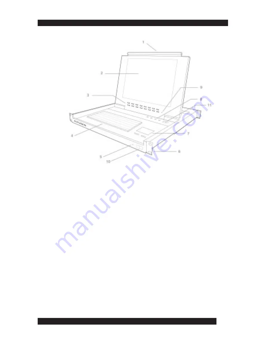
KL0116 Front View
1. Handle
• Pull the handle to slide the KVM module out. Push to slide the module in.
2. LCD Screen
• After sliding the KVM module out, flip the cover to access the LCD monitor.
3. Port LEDs
• Each port LED provides status information about corresponding CPU ports. The top
LED row corresponds to Port 1- 8 and the bottom LED row to Ports 9 - 16. Each Port
consists of a left and right LED pair:
On Line
LED (left port) and
Selected Port
LED
(right port). The following describes the LED light indicators:
- A GREEN
On Line
LED indicates the corresponding attached computer port is
up and running
- A RED
Selected
LED indicates the corresponding attached computer has the KVM
focus. Under normal conditions, the LED is steady. When accessing its port under
Auto Scan Mode
(see page 21) the LED flashes.
- Each time the KL0116 powers on, the Switch performs a self-test. The
On Line
and
Selected
LEDs blink once in succession during the self-test.
4. Keyboard
5. Power LED
• The Power LED lights blue when the KL0116 powers up and is ready to operate
6. Rack Mounting Brackets
• Rack mounting brackets are included to secure the chassis to a system rack
Summary of Contents for Altusen KL0116
Page 1: ...1 ...
Page 2: ...2 ...
Page 10: ...10 8 ...
Page 40: ...40 38 ...
Page 45: ...45 Click Cancel to close the Firmware Upgrade Utility 43 ...
Page 46: ...46 44 ...
Page 60: ......


