background image

SECTION  502-61 0-418 

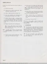
Install  the  wiring  board  and  plug  assembly  as 
follows: 

(1) 

Remove  set  housing. 

(2)  Loosen  screws  on  dial  mounting  plate.  Move 

mounting  to  left  and  lift  out. 

(3)  Remove  right-hand  dial  mounting  screw. 

(4)  Place  dial  mounting  screw  through  hole  in 

wiring  board and  replace  screw  in  dial. 

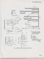
(5)  Connect  plug  assembly  to  chaining  switch 

of  third  module  (636-type)  or  fifth  module 

(637-type)  and  terminate  (G-V)  and  (V-G)  leads 
of  plug  (Fig.  3).  Insulate  and  store  unused  plug 
leads. 

(6)  Replace  and  secure  dial  mounting  plate. 

Note: 

If more than  one  busy lamp  is required, 

order  a  6C  KTU  and  use  busy  lamp  control 

circuit shown in  Fig.  5. 

2.09 

A  D-180411  Kit  of  Parts  is  required  when 

Priority  Hold 

is  to  be  furnished.  Install 

as  follows: 

(1)  Connect  contact  strips  to  635A5C  key.  Plug 

pink  plug  into  hold  position  on  key. 

Page  2 

(2)  Disconnect  all  mounting  cord  plugs  and  the 

two  contact strips  [sets equipped  with D120K 

(MD)  or  D200S  (MD)  mounting  cords]  from  the 
second  module,  remove  key  and  replace  with 

635A5C key. 

(3)  Reterminate contact strip  leads  and connnect 

mounting  cord  plugs  with  exception  of  white 

plug  which  is insulated and  stored. 

Note: 

Contact  strips  are  not  required  with 

sets equipped with  D120M or D200AA mounting 

cords. 

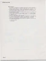
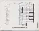
(4)  Rearrange  wiring  per  Fig.  4. 

Hold  key  in  first  module  is  used  as  regular  hold 

or  if  required, 

I Hold. 

Second  key  is  used  for 

Priority Hold. 

3. 

MAINTENANCE 

3.01 

For maintenance information, refer to Division 
502  section  entitled  630,  1630,  and  2630 

Series  Telephone  Sets-Common  Installation  and 
Maintenance  Information.  Individual  components 
such  as  dials,  keys,  ringers,  etc.  are  covered  in 
sections pertaining  to  the  particular  item. 

3.02 

Do  not  use  solvents  to  clean  plastic  parts 
of  these  sets.  Use  a  damp  cloth  only.  If 

discolored,  replace  part. 

BSP S02-610-418-i04_1975-03-02.jpg  Scanned  by  Frank  Harrell, (Cowboy  Frank) Castle  Rock, Colorado  Feb  04,2012  14:34:45 

Summary of Contents for 636CA

Page 1: ...key and will replace the 840151120 and 840151138 assemblies supplied with the 635A5C key 2 03 Because of the physical arrangement of the 635 type key the contact strips do not extend to the chaining switch This requires a second tip and ring to each module except the last See Fig 2 sheets 1 through 5 2 04 Mounting cords of these CALL DIRECTOR sets terminate in individual plugs connected to the rea...

Page 2: ...ting cord plugs and the two contact strips sets equipped with D120K MD or D200S MD mounting cords from the second module remove key and replace with 635A5C key 3 Reterminate contact strip leads and connnect mounting cord plugs with exception of white plug which is insulated and stored Note Contact strips are not required with sets equipped with D120M or D200AA mounting cords 4 Rearrange wiring per...

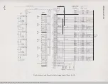
Page 3: ..._ ______ TO G Bll J BUZZER BL 6 2 2 GN NOTES I TO CONTACT STRIPS 1ST MODULE 2 TO CHAINING SWITCH I ST MODULE 3 NIA RINGER SHOWN TIA RINGER HAS 51 NGLE COIL 200 OHMS AND ONLY R AND BK LEADS LEGEND DP FL HS LS ON 01 Al PULS flASH K Y H AOS T JACKS LIN SWITCH OH NORMAL DIAL I NSULAT D AND STOR O NETWORK TERM1 NAL J UNDESIGNATEO AMPLIfI R T RMI NAL T RMI NALS AR ON T RM BOARD 40108 OR 422BF NETWORK Fi...

Page 4: ... 4 WHEN THE 658A KEY I S REQU I RED AS A DUAL PURPOSE KEY REMOVE STRAP BETWEEN TERM I NALS 17 AND 18 USE MIW CORD OR EQUI VALENT TO CONNECT TERMINAL 17 TO A D ISS I M I LAR GROUND OR NONGROUNDED CIRCUIT 5 TO SUPPLY I HOLD FEATURE TERMI NATE O Y MOUNTING CORD LEAD FROM F I RST MODULE ON TERMINAL 24 LEAD BECOMES SP LEAD AT EQUIPMENT 6 I F HOLD POSITION LAMP IS REQUIRED CONNECT G Y LAMP LEAD AND Y G ...

Page 5: ... 04 2012 14 35 56 Y S Y BR BR Y f J 0 Y Y O c v f J G BK BK G BR BK 81 BR S BK BK S s R R S BL BK BK BL f J o R R 0 G R iR G BR R R BR BR W W BR s w w s BL R R BL BL W W BL o w w o s lBL V 5 V BL l l BR V r e i R R R1 8 OR Bt BL SG R T B A H S OR Sl L LG R T B A H S OR I L LG R T B A1H1S OR 51 L LG R T B A1H S OR Sl L LG R T 6 A H S OR Sl L LG I R T OR B A1H15 OR 51 L LG TO lA IAI IA2 KTS A75A ONL...

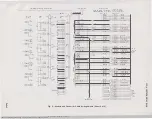
Page 6: ...6 17 42 18 43 13 36 39 15 40 10 35 II 36 12 37 1 32 33 34 29 s 30 6 31 26 2 27 3 28 21 22 47 23 24 49 2S 50 A75A OR AIOOD CONNECTOR C t BLE 0 W B I ND CONN 2 IS Y Y 5 Bl Y Y BL D Y Y O G Y J BK G BR BK BK ml f J S R R S BL BK BK BL 0 BK BK D O R 5 R 0 G R R G BR R l W BR S W 5 t JJ IR BL BL W rJ BL o wl w o l l 5 BL V V BL V 0 G V V G fi R l V BR s v BZ BZI SPARE P6 R T A H S OR 51 l OR 56 LG OR 5...

Page 7: ... Y lY eRJ s v Y i BL Y Y BL 112 t l l t ol fG ll Y G G BK BK G jBR BK BK BR 5 BK jBK 5 S R R S BL BK fBK BL 0 BK BK 0 O R R 0 G R jR Gj s BR W W BR s w jw sl BL R jR Bl BL W s t Bl o w s W G SPARE SPAR SPARE se aBE R T B A H SOR 51 I LG R T B A H 5 OR 51 l LG R T 8 A1H1SOR 51 l LG R T B H SOR il l LG R T B A1H1SORSI l LG R T B A1H1SOR 51 l LG II 0 CQ CD Fig 2 Module and Connector Cable Arrangement...

Page 8: ...BLE BR Wl BINDER PLUG4 CONN4 I 19 l t 44 S Y 1 20 Y S I BL Y BL Y SPARE SPARE SPARE SPARE Y Rl 4l 1 Y B l T ___ _ Y O y l7 O tY 42 Y O A H S OR 51 1 8 G Y I OR S6 Y G 43 Y G LG OR 5 1 2 G BK 13 G BK BK G Fig 2 Module ond Connector Coble Arrangements Sheet 4 of 5 SSP 502 610 418 i04_197S 03 08 jpg Scanned by Frank Harrell Cowboy Frank Castle Rock Colorado Feb 04 2012 14 37 01 TO lA IAI IA2 OR 6A KT...

Page 9: ...ll BL R R BL BL Wl W 8L I w o G W W G 7 f 4 CONNECTOR CABLE A75A G W BINOER AI000 S W 8INOER 35 tR 51 BL BK II jBI BLj 36 0 BI J 12 81 0 37 O BI 7 32 R 0 B G Rl 33 IR G 9 IBR R 34 R BR 4 BB Wl 29 W BR 5 S W 30 lw sr 6 BL R 31 R Bll I BL WI SPAR SPARE SPARE SPARE R OR 66 1 OR LG4 8 6t 1SQBSl L 54 OR LIO LG SID OR LGIO R OR 63 T OR LG3 8 A H S OR 1 L 53 ORL9 LG 59 ORLG9 R OR LZ T OR LG2 B A H 5 OR 5...

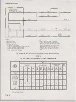
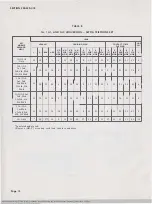
Page 10: ...N ONE BUSY LAMP IS REQUI REO ONLY THE 6C KTU BUSY LAMP CONTROL CIRCUIT SHOWN IN FIG 5 MAY BE USED Fig 3 Statian Busy lamp Circuit Using Printed Wiring Board Assembly TABLE A lA I AI AND 1A2 CONVERSION 636CA TELEPHONE SET LEAD KEY HOLD KEY CHAINING PLUG CONTACT STRIP MODULE OR PLUG ARRANGE MENT V G V G R R R R R y G BR V V BR 1ST 2ND 1ST 2ND 1ST 2ND 3RD MOD MOD MOD MOD MOD MOD MOD 1Al 1A2 10 10 5 1...

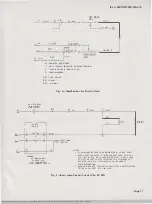
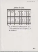
Page 11: ...__ o __j GRD I I T c Jl GRD LEGEND PU PICKUP KEY H HOLD KEY LS LlNE SWITCH HSIA HEADSET JACK A L rBUSY LAMP NOTE 21 LG NOTES I Y BRI MOUNTING CORD LEAD DESIGNATED BL IS NOT USED 2 WHEN A LAMP IND ICATOR IS USED FOR BUSY LAMP EITHER A 51A IOV OR 52A 24V LAMP MAY BE USED IF THE LAMPS OF A KEY OR LAMP SOCKET INSTALLED IN A TELEPHONE SET ARE USED ONLY 51 A IOV LAMPS SHALL BE USED TO AVOID OVERHEATING ...

Page 12: ... 41 14 5 15 35 12 9 11 21 31 9 11 21 31 14 8 3rd 4th Mod 1A 5th Mod 1A1 1A2 1st 2nd 3rd Mod 10 12 31 14 5 15 12 45 9 11 21 14 9 11 21 14 41 8 1A 4th 5th Mod 1A1 1A2 1st 2nd Mod 10 12 21 14 5 12 35 45 9 11 14 31 9 11 14 31 41 8 1A 3rd 4th 5th Mod 1A1 1A2 1st Mod 1A 2nd 3rd 10 12 11 14 12 15 35 45 9 14 21 31 9 14 21 31 41 8 4th 5th Mod 1A Only 10 37t 13 5 15 35 45 37 11 21 31 37 11 21 31 41 18 Insul...

Page 13: ...9 18 39 30 39 30 39 30 39 30 39 1 When using converted 6th pickup button as common signaling key remove in sulate and store Y 0 mounting cord lead from terminal 39 2 If more than six signal keys are required replace 635G5C key with a 658A key If more than five private or intercom lines are required convert keys in 2nd 636CA or 4th 637DA module in same order Connect plug leads to terminal 39 to uti...

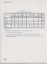
Page 14: ...ay Grd Note 4 Insulate and store Notes 1 Remove BR BK and BK BR slate plug leads from terminals 10 and 29 insulate and store 2 To individual line or common ringer circuit at equipment 3 To external ringer or buzzer Connect ringer or buzzer circuit to Bl Y Y BL connector cable leads at equipment 4 Connect T R and A leads from equipment and station to be cut off through contacts of auxiliary relay C...

Reviews: