background image

40

INSTALLATION

The appliance must be installed by qualifi ed 
staff working in accordance with the regula-
tions in force.
Before installing, ensure that the appliance 
is  correctly  preset  for  the  local  distribution 
conditions (gas type and pressure).
The presettings of this appliance are indicat-
ed on the nameplate shown on the cover.
This appliance is not connected to a fl ue gas 
extractor  device.  It  must  be  installed  and 
connected  in  accordance  with  the  regula-
tions in force.
This  appliance  may  only  be  installed  and 
may  only  operate  in  rooms  permanently 
ventilated in accordance with national regu-
lations in force.

VENTILATION

The rooms in which gas appliances are in-
stalled must be well ventilated in order to al-
low correct gas combustion and ventilation.
The air fl ow necessary for combustion is at 
least 2 m

3

/h for each kW of rated power.

POSITIONING

Remove the packaging accessories, includ-
ing the fi lms covering the chrome-plated and 
stainless steel parts, from the cooker. 
Position the cooker in a dry, convenient and 
draft-free place. Keep at an appropriate dis-
tance from walls which may be damaged by 
heat (wood, linoleum, paper, etc.).
The cooker may be free-standing (class 1) 
or between two units (in class 2 st 2-1) the 
sides of which must withstand a temperature 
of 100°C and which must not be higher than 
the working table.

CONNECTING TO THE GAS SUPPLY

Before connecting the cooker, check that it 
is preset for the gas to be used.
The  connection  is  on  the  right;  if  the  pipe 
has to pass behind the cooker, it must be 
kept  low  down  where  the  temperature  is 
about 50°C.

Rigid connectio

n (see fi g. 3 A and B)

  The  connection  to  the  mains  gas  supply 

may be made using a rigid metal pipe or 
with a metal hose. Remove the hose con-
nector (if already fi tted) and screw the rigid 
union onto the threaded connection of the 
gas train (see fi g. 3 A). The union for rigid 
connection  may  already  be  fi tted  on  the 
gas train, or may be amongst the cooker 
accessories. Otherwise, it can be obtained 
from your dealer.

  If national regulations permit, a metal hose 

complying with the national standards can 
be screwed directly onto the threaded con-
nection of the gas train, fi tting a seal (see 
fi g. 3B).

  However, users are strongly recommended 

always to fi t the rigid union.

-  Connection using a rubber hose

 (see fi g. 

3 C and D)

  Connect a rubber hose carrying the con-

formity mark currently in force to the hose 
connector. The hose must be replaced at 
the date indicated at the latest, and must 

be secured at both ends using standard 
hose  clamps.  It  must  be  absolutely 
accessible to allow its condition to be 
checked along its entire length.

CAUTION:
- Use of the hose connector is only per-

mitted for free-standing installation.  If 
the appliance is installed between two 
class 2 st. 2-1 unions, the rigid union is 
the only form of connection permitted.

IMPORTANT:
- After  installation,  check  that  the  con-

nections are airtight.

- Use only standard rubber hoses.
- Avoid sharp bends in the pipe and keep it 

well way from hot surfaces.

- References to the regulations covering the 

gas connection to the appliance: ISO 7-1 
(NL)

CONNECTING  TO  THE  ELECTRICAL 
MAINS

Before making the connection, check that:
- the  mains  voltage  is  as  indicated  on  the 

Installation

GB

Summary of Contents for 50N Series

Page 1: ...mbi und Elektroherde Serie Installations und Bedienungsanleitung für Gas Kombi und Elektroherde Serie Installations und Bedienungsanleitung Notice d installation et d utilisation des cuisinières à gaz mixtes et électrique Séries Instructions for use and maintenance of gas gas electric and electric cookers Series Instructions for use and maintenance of gas gas electric and electric cookers Series I...

Page 2: ...die U er terecht tijdens de aankoop aan heeft gesteld U wordt daarom verzocht de instructies in deze handleiding goed te lezen en nauwgezet op te volgen het spreekt vanzelf dat uitsluitend die paragrafen in beschouwing dienen te worden genomen die betrekking hebben op accessoires en bedieningsknoppen welke op Uw apparaat aanwezig zijn De fabrikant onthoudt zich van elke aansprakelijkheid voor scha...

Page 3: ...én of meer branders van de kookplaat Elektrische ontsteking van de bovenste branders Elektrische ontsteking van de branders van de oven en grill Thermostaat of kraantje voor de oven Elektrische ovenverlichting Draaispit Brander van de grill Mechanische keukenwekker Programmering einde kooktijd met één enkele knop Eén of meer elektrische plaatjes Voor de POSITIES VAN DE BRANDERS zie figuur 1 op het ...

Page 4: ...ogen zijn dan het werkblad AANSLUITING OP DE GASTOEVOER Controleer alvorens de aansluiting op het gasnet uit te voeren of het fornuis geschikt is voor het type gas waarmee het zal worden gevoed De aansluiting wordt aan de rechterkant van het fornuis uitgevoerd Als de slang achterlangs moet lopen moet deze langs de onderkant van het fornuis lopen omdat hier de temperatuur ongeveer 50 C zal bedragen...

Page 5: ...gebruikt zie schema s fig 2 BELANGRIJK de fabrikant onthoudt zich van enige verantwoordelijkheid voor scha de veroorzaakt door het niet naleven van de voorschriften en geldende normen Het wordt aanbevolen de correcte aansluiting van de aardverbinding van het apparaat te controleren zie schema s fig 2 FORNUIZEN UITGERUST MET ELEKTRI SCHE ONTSTEKING De juiste afstanden tussen de elektrode en de brande...

Page 6: ...rd de natuur lijke ontluchtingsopeningen geopend laten of een gedwongen afzuigkap installeren Bij een langer en intensief gebruik kan een extra ventilatie noodzakelijk blijken zoals bijvoorbeeld het openen van een raam of een meer efficiënte ventilatie door bijvoor beeld het vermogen van de afzuigkap te vergroten ONTSTEKING VAN DE BRANDERS OP DE KOOKPLATEN Op de knop drukken en naar links draaien t...

Page 7: ...op de knop te drukken die zich op het bedieningspaneel bevindt of door op de knop van de brander te drukken die moet worden aangestoken Indien de elektrische ontsteking bij bepaalde gassoorten moeizaam gaat is het raadzaam de handeling met de knop op de minimum stand kleine vlam uit te voeren Bij fornuizen uitgevoerd met een elektrische ontsteking van de oven en grill is het absoluut noodzakelijk ...

Page 8: ...UIK VAN DE GASOVEN Na de brander te hebben ontstoken de oven gedurende 10 minuten laten verwarmen de te koken levensmiddelen in een normale ovenschotel doen en op het verchroomde rooster plaatsen het geheel indien mogelijk in de 3e positie in de oven stoppen en de wijzer van de knop op de gewenste stand zetten de kookfase kan door het venster van de deur en met de verlichte oven worden gecontrolee...

Page 9: ...f om rechtstreeks vlees op te grilleren De druippan dient uitsluitend voor het opvangen van sappen afkomstig van de gerechten en mag nooit als kookpan worden gebruikt De oven of de grill worden met behulp van een enkele knop aangestoken Vanuit de stand 0 uit en door de knop rechtsom te draaien worden de volgende standen verkregen symbool standen verkregen ontsteking van de ovenverlichting die ook ...

Page 10: ...l thermostaatregeling ontsteking van de grill bovenin de oven Om de wijzer van de knop op de 0 stand te zetten uit dient de knop linksom te worden gedraaid NOTA Het gele controlelampje zal gaan branden afhankelijk van de stand van de thermostaat Alvorens de te koken levensmiddelen in de oven te plaatsen moet de oven gedurende ten minste 10 minuten worden voorverwar md ELEKTRISCHE MULTIFUNCTIEOVEN ...

Page 11: ... behulp van de thermostaatknop ingesteld symbool of ontsteking van de grill bovenin de oven de knop van NL Voor de gebruiker de thermostaat moet in de hoogste stand staan symbool of infrarood koken met bekrachtigde grill aanbevolen voor grotere spijzen de knop van de thermostaat moet in de hoogste stand staan symbool snelkoken met geventileerde oven de knop van de thermostaat moet in de hoogste st...

Page 12: ... niet hitte bestendige voorwerpen zoals hout papier spuitbussen lucifers enz in op te bergen Regelmatig de rubberen toevoerslang controleren en erop toezien dat zij niet te dicht langs hete wanden loopt geen knikken heeft of ingeklemd is en verder in goede staat verkeert Op uiterlijk de aangegeven datum moet de slang worden vervangen en moeten de twee uiteinden met behulp van genormaliseerde slang...

Page 13: ...t bereiden van gerechten Bij koken en braden worden de branders heet Let op als er kinderen in de buurt zijn De ovenruit kan door langdurig gebruik van NL Voor de gebruiker de oven op de maximale temperatuur bijv bij het grilleren warm worden Let op als er kinderen in de buurt zijn Vet en olie zijn bij oververhitting ontvlam baar Blijf in de buurt tijdens het bereiden van gerechten Gebruik het toe...

Page 14: ...ement Zet de afdekplaat altijd omhoog bij gebruik van de kookplaat Alvorens de afdekplaat omhoog te zetten moet u er voor zorgen dat deze droog is Laat het toestel afkoelen voordat u de afdekplaat sluit Wees voorzichtig met licht ontvlambare materialen in de omgeving van het toestel denk bijvoorbeeld aan kleding ALGEMENE INFORMATIE Over temperaturen bij het gebruik van een fornuis Elektro en gasfo...

Page 15: ...acht op het product zelf typeplaatje het product zelf typeplaatje Dit symbool wijst erop dat het product in overeenstemming met de geldende nor men is geclassificeerd als elektrische of elektronische apparatuur en conform is aan de Richtlijn 2002 96 EG AEEA en dus op het eind van de nuttige levensduur ervan verplicht apart van het huishoudelijke afval zal moeten worden behandeld door koste loze ov...

Page 16: ... Ihr neues Gerät optimal nutzen können empfehlen wir Ihnen die Anweisungen des vorliegenden Handbuchs genau zu befolgen Selbstverständlich müssen Sie nur die Anweisungen berücksichtigen die sich auf die Ausstattung und die Bedieneinrichtungen beziehen über die Ihr Gerät verfügt Der Hersteller haftet nicht für Schäden an Sachen oder Personen die auf eine nicht fachgerecht ausgeführte Installation o...

Page 17: ...e 2 0 kW Schnellkochplatte LEISTUNG ELEKTROBACKOFEN Backofen 1 5 kW unten 0 7 kW oben 2 2 kW Grill 2 0 kW Kat siehe Typenschild auf Deckblatt Klasse 1 bzw 2 1 Herde der Wärmeschutzklasse X AUSSTATTUNG Alle Modelle verfügen über Zündsicherungen für Backofen und Grill Je nach Modell können die Herde außerdem über folgende Einrichtungen verfügen Zündsicherung für einen oder mehrere Brenner der Kochmu...

Page 18: ...lußstutzen kann bereits montiert sein oder befindet sich unter den Zubehörteilen des Herdes Anderenfalls kann er beim Händler bestellt werden Falls dies von den im Aufstellungsland geltenden Vorschriften erlaubt ist kann das Metallrohr bzw der Metallschlauch auch unter Einlegung eines geeigneten Dicht ringes direkt auf den Gewindestutzen der Speiserampe aufgeschraubt werden s Abb 3 B Es wird jedoch...

Page 19: ...rochen oder Mantel beschädigt Zündfunke wird nach Erde abgeleitet bei anderen Teilen des Herds Zündtransformator oder Mikroschalter defekt Luftansammlung in den Leitungen vor allem nach längerer Nicht Verwendung des Herdes Luft Gas Mischung nicht korrekt schlechte Vergasung ZÜNDSICHERUNG Der richtige Abstand zwischen dem Fühler des Thermoelements und dem Brenner ist in den Abbildungen 4 5 und 6 an...

Page 20: ...drücken und gegen den Uhrzeigersinn bis zum Symbol Großstellung drehen Ein brennendes Streichholz durch das mittlere Loch des Backofenbodens an den Brenner annähern und den Bedienknebel ganz eindrücken siehe Abb 7 Durch die zentrale Öffnung des Bodens kontrollieren ob der Brenner gezündet hat Hierbei weiterhin den Bedienknebel gedrückt halten Nach ca 10 Sekunden den Bedienknebel loslassen und sich...

Page 21: ...ng gebracht wurde Bei der ersten Inbetriebnahme des Backofens bzw des Grills ist es möglich daß ein eigenartiger Geruch oder Rauch aus der Backofenmuffel austritt Dies ist auf harz und ölhaltige Rückstände an den Brennern zurückzuführen BENUTZUNG DER KOCHSTELLEN DER GASKOCHMULDE Das verwendete Kochgeschirr muß einen dem Brenner entsprechenden Durchmesser aufweisen Die Flammen sollten nie über den ...

Page 22: ...auch die andere Seite der Infrarotstrahlung auszusetzen ANMERKUNG bei der ersten Inbetrieb nahme tritt Rauch aus der Backofenmuffel aus Daher sollte man abwarten bis alle Ölrückstände auf dem Brenner vollständig verbrannt sind bevor man das Grillgut in den Backofen gibt Der Grill darf nur mit seiner Nennwärme be lastung benutzt werden ACHTUNG Das Gerät erreicht bei Grillbe trieb sehr hohe Temperat...

Page 23: ...eßes in die Nabe des Motors einstecken Den Griff des Spießes abschrauben Die Fettpfanne in die unterste Einschub leiste schieben Die Backofentür nur teilweise bis zum Wrasenabweisblech schließen Den Motor des Drehspießes mit dem entsprechend gekennzeichneten Schalter einschalten Das Fleisch ab und zu mit Fett bestreichen Am Ende der Grillzeit den Griff auf den Drehspieß schrauben und den Spieß aus...

Page 24: ...schließlich zum Auffangen der vom Grillgut abtropfenden Flüssigkeiten Sie darf nie als Kochgeschirr verwendet werden WenngleichzeitigaufzweiEbenengebacken gebraten wird ist zu berücksichtigen daß sich die Garzeiten ändern können BENUTZUNG DES MULTIFUNKTIONS ELEKTROBACKOFENS Dank der verschiedenen Heizelemente die über einen thermostatgeregelten Wahlschal ter gesteuert werden bietet dieser Backofen...

Page 25: ... Garzeit Funktionsweise DE Für den Benutzer Den Drehknopf auf die gewünschte Garzeit einstellen max 120MinutenbeiElektroback öfen max 100 Minuten bei Gasbacköfen Den Temperaturregler auf die gewünschte Temperatur und den Funktionswahlschalter auf die gewünschte Beheizungsart einstellen Wenn der Drehknopf der Zeitschalt automatik die Stellung 0 erreicht ist der Garvorgang beendet Die Beendigung des...

Page 26: ...digen DE Für den Benutzer RICHTLINIE 2002 96 EG WEEE IN FORMATIONEN FÜR DEN ENDVER BRAUCHER Fig A Die folgenden Informationen dienen nur den ie folgenden Informationen dienen nur den Endverbauchern die ein Produkt besitzen Endverbauchern die ein Produkt besitzen auf dem das u a Symbol Fig A angegeben auf dem das u a Symbol Fig A angegeben ist Dieses Symbol befindet sich auf dem ist Dieses Symbol be...

Page 27: ...6 EC DEEE 37 Figures 48 50 FR Nous vous remercions d avoir choisi un appareil de notre marque Veuillez lire attentivement cette notice pour bénéficier des performances que vous êtes en droit d en attendre Notre Société ne sera pas responsable des dégâts causés par une installation incorrecte ou par une mauvaise utilisation de l appareil Afin de produire des appareils de plus en plus conformes aux te...

Page 28: ...Dimensions Four Four avec Dimensions Four Four avec utilisables ventilateur utilisables ventilateur utilisables ventilateur utilisables ventilateur utilisables ventilateur utilisables ventilateur Largeur cm 39 5 cm 39 5 Largeur cm 39 5 cm 39 5 Largeur cm 39 5 cm 39 5 Profondeur cm 42 0 cm 40 0 Profondeur cm 42 0 cm 40 0 Profondeur cm 42 0 cm 40 0 Profondeur cm 42 0 cm 40 0 Profondeur cm 42 0 cm 40...

Page 29: ...la cuisinière vérifier qu elle a été réglée pour le type de gaz avec lequel elle sera alimentée Le raccordement de l appareil se fait à droite Si le tuyau doit passer derrière l appareil il doit passer en bas loin des parois du four Dans cette zone la température est de 50 C environ Raccordement rigide voir fig 3 A et B Le raccordement peut être fait avec un tube métallique rigide ou flexible Pour ...

Page 30: ...cte voir schèmes fig 2 à la fin de la notice CUISINIERES AVEC ALLUMAGE ELECTRIQUE La distance correcte entre l électrode et le brûleur est indiquée dans les figures 4 5 6 Si l étincelle ne jaillit pas il ne faut pas insister on peut endommager le générateur Causes possibles de mauvais fonctionnement bougie humide encrassée ou cassée distance électrode brûleur inexacte fil conducteur de la bougie cassé...

Page 31: ...exemple en ouvrant une fenêtre ou une aération plus efficace par exemple en augmentant la puissance de la ventilation mécanique si elle existe ALLUMAGE DES BRULEURS DE LA TA BLE DE CUISSON Appuyer sur la manette et la tourner en sens inverse à la marche des aiguilles d une montre jusque vers le repère sens inverse à la marche des aiguilles d une marqué sur le bandeau flamme au maximum entretemps app...

Page 32: ...r Si l allumage électrique est difficile pour quel ques types de gaz il est conseillé d effectuer l opération avec la manette sur position minimum flamme au ralenti Pour les cuisinières équipées de dispositif d allumage électrique des brûleurs du four et grilloir il faut absolument allumer ces brûleurs avec la porte du four complète ment ouverte Pendant l allumage des brûleurs de four et grilloir qu...

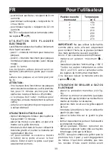
Page 33: ...on à travers le hublot de la porte et avec le four éclairé Eviter d ouvrir la porte sauf pour assaisonner les mets Position manette Température thermostat en C 1 150 2 170 3 190 4 210 5 230 6 250 7 270 IMPORTANT Ne pas utiliser la lèche frite comme plat à cuire elle sert uniquement pour contenir l huile ou la graisse tombant des mets pendant la cuisson au grilloir NOTE Pour cuisinières sans thermo...

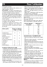
Page 34: ...ge du grilloir avec fon ctionnement du tournebroche La remise à 0 éteint s effectue en tournant la manette dans le sens inverse des aiguilles d une montre NOTE Le voyant jaune s allume lorsque le thermostat intervient Avant d introduire les mets à cuire préchauf fer le four pendant 10 minutes au moins Position manette Température thermostat en C 1 60 2 80 3 110 4 140 5 170 6 200 7 220 8 250 UTILIS...

Page 35: ...un ou deux niveaux les tempéra tures du four se réglent tournant la manette du thermostat repère ou allumage du grilloir sur le plafond du four la manette du thermo stat doit être en position de temperature maximale Dans toutes les positions excepté le 0 le vo yant rouge et la lampe du four s allument REMARQUE Le voyant jaune s allume lorsque le thermostat intervient Avant d introduire les mets à ...

Page 36: ...ns le sens des aiguilles d une montre A la fin du temps programmé un signal sonore se met en marche UTILISATION DU PROGRAMMATEUR DE Pour l utilisateur FR FIN CUISSON MONOCOMMANDE SANS HORLOGE fig 13 Il permet de programmer la durée de cuisson Fonctionnement Positionner la manette sur le temps de cuisson souhaitée 120 minutes maxi pour four électrique 100 minutes maxi pour four à gaz Choisir la tempé...

Page 37: ...DEEE IN FORMATIONS POUR L UTILISATEUR Fig A Ces informations s adressent exclusivement aux utilisateurs possédant un produit sur aux utilisateurs possédant un produit sur lequel figure le symbole ci dessous Fig A lequel figure le symbole ci dessous Fig A Ce symbole est reporté sur l étichette des Ce symbole est reporté sur l étichette des caractéristiques techniques de l appareil caractéristiques te...

Page 38: ... 90 396 EEC 73 23 and 93 88 EEC 89 336 radio frequency inter feren ce EEC 89 109 contact with foods 2002 96 EC WEEE FOREWORD Refer only to the headings and sections covering accessories actually installed on your cooker Technical data and specifications 39 Installation 40 41 Ventilation 40 Positioning 40 Gas connection 40 Electrical connection 40 Electric ignition 41 Safety device 41 For the user 4...

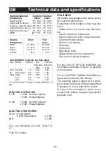
Page 39: ...50 0 GAS BURNERS injectors and flow rates Gas Burner Injector low nominal flow rate flow rate kW kW G25 auxiliary 75 0 40 0 90 25 semi rapid 105 0 40 1 85 mbar rapid 132 0 85 3 00 oven 132 1 00 3 00 grill 116 2 00 For thermostat In case of oven with tap 1 3 kW ELECTRIC HOTPLATES ø 145 1 0 kW Normal hotplate 1 5 kW Rapid hotplate ø 180 1 5 kW Normal hotplate 2 0 kW Rapid hotplate ELECTRIC OVEN POWER O...

Page 40: ...d the cooker it must be kept low down where the temperature is about 50 C Rigid connection see fig 3 A and B The connection to the mains gas supply may be made using a rigid metal pipe or with a metal hose Remove the hose con nector if already fitted and screw the rigid union onto the threaded connection of the gas train see fig 3 A The union for rigid connection may already be fitted on the gas train...

Page 41: ...t correct spark plug wire broken or without sheath ing spark discharging to earth to other parts of the cooker generator or microswitch damaged air has built up in the pipes particularly if the cooker has been out of use for a long time air gas mixture incorrect poor fuel set ting THE SAFETY DEVICE The correct gap between the end of the ther mocouple sensor and the burner is shown in figures 4 5 an...

Page 42: ... after about 10 seconds release the knob and check that the burner remains on Otherwise repeat the operation IGNITING THE GRILL BURNER GAS GRILLS Fit the control knob guard as shown in fig 10 press the oven knob and turn it to the right until it reaches the stop move a burning match towards the perfo rated burner pipe and press the knob right down see fig 8 check that the burner has ignited keeping ...

Page 43: ...t used leave for about 10 minutes to dry oil or moisture residues if the hotplate is to be out of use for a long time apply a little grease to its painted sur face do not allow spills to burn onto the hotplate requiring the use of abrasive cleaners HOW TO USE THE GAS OVEN After igniting the burner leave the oven to heat up for about 10 minutes place the food for cooking in an ordinary oven dish an...

Page 44: ... a pan for cooking foods under the grill The drip tray is only there to collect any juice from foods and must never be used as a cooking surface There is a single control knob for the oven or grill Starting from the 0 off position the knob can be turned clockwise to the following settings be turned clockwise to the following settings symbol oven lamp on it will remain on symbol oven lamp on it wil...

Page 45: ...on static oven c Infra red rays grill Starting from the position 0 off the selector knob can be turned clockwise to the follow ing positions symbol ing positions oven light and red warning light on symbol or conventional static oven cooking the oven temperature is controlled using the thermostat knob symbol or controlled using the thermostat knob cooking with fan oven on one or two levels the oven...

Page 46: ...ll serve as a guide bearing in mind that cooking times and temperatures may vary depending on the type and amount of foods cooked and personal taste OVENS WITH THERMOSTAT If cooking temperatures are not as set call in an engineer to check the thermostat HOW TO USE THE MINUTE MINDER Fig 12 Set the cooking time considered necessary by turning the timer knob clockwise An alarm will sound at the end o...

Page 47: ...on is strictly addressed to those who have a product showing the symbol be who have a product showing the symbol be low Fig A This symbol is indicated on the low Fig A This symbol is indicated on the technical data sticker rating label placed on technical data sticker rating label placed on the product itself the product itself This symbol indicates that the appliance is considered as Waste Electr...

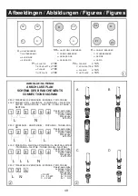
Page 48: ...nitt Section câble Leiterquerschnitt Wire gauge 3 5 kW 3x2 5 mm Wire gauge 3 5 kW 3x2 5 mm Wire gauge 2 Wire gauge 2 Wire gauge 2 2 3 5 kW 3x1 5 mm 3 5 kW 3x2 5 mm 2 2 3 5 kW 3x1 5 mm 3 5 kW 3x2 5 mm 2 0 2 2 kW 2 2 3 5 kW 3x1 5 mm 0 2 2 kW 2 2 3 5 kW 3x1 5 mm 3x1 mm 2 2 3 5 kW 3x1 5 mm 3x1 mm 2 2 3 5 kW 3x1 5 mm 2 1 3 4 5 2 L N 1 3 4 5 2 L L L L N L L 1 3 4 5 2 1 3 5 kW 3x2 5 mm 3 5 kW 3x2 5 mm 2 ...

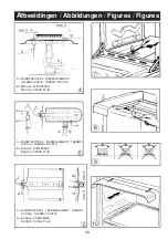
Page 49: ...H B A mm 3 mm 3 mm 3 mm 3 mm 3 A WARMTEKOPPEL THERMOELEMENT THERMO COUPLE THERMO COUPLE B BOUGIE ZÜNDKERZE BOUGIE SPARK PLUG 5 5 1 5 mm 1 5 mm 2 mm 4 mm 4 mm A A B B A WARMTEKOPPEL THERMOELEMENT THERMO A WARMTEKOPPEL THERMOELEMENT THERMO COUPLE THERMO COUPLE B BOUGIE ZÜNDKERZE BOUGIE SPARK PLUG 7 7 7 7 10 10 8 9 Afbeeldingen Abbildungen Figures Figures ...

Page 50: ...50 11 12 12 12 12 15 45 60 30 13 Afbeeldingen Abbildungen Figures Figures 14 14 14 ...

Page 51: ...51 ...

Page 52: ...52 ED 20 06 2005 334821 02 ...

Reviews: