background image


Asycube Control URCap 

User guide 

© 

Copyright Asyril S.A. 

Standard use of the Asycube Control URCap 

Version: A2 


000.102.083 


24/50


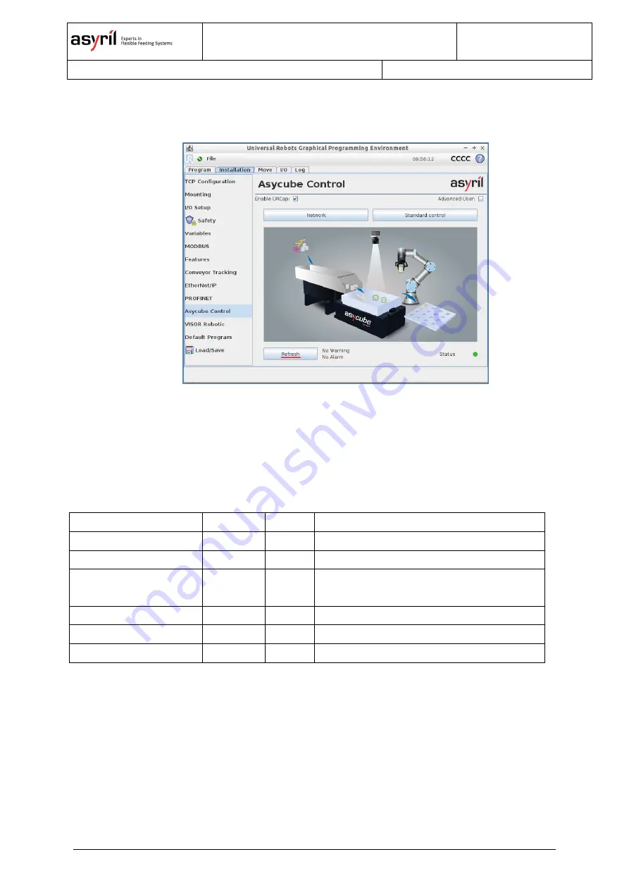
The 

Refresh

  button,  located  at  this  level,  allows  the  URCap  to  retrieve  and  reinitialize  the 

current warnings and alarms at any time. 


Figure 3-17 

– Refresh button to retrieve at any time warnings & alarms 

The execution of a UR program is stopped each time a warning or an alarm is returned by the 

Asycube platform. A popup is then displayed, inviting the user either to stop the program or to 

continue it. In both cases, the warning or alarm is reinitialized by the Asycube platform. 


The current list of warnings and alarms is the following: 

Define 

Type 

Value 

Comment 

WARNING_FLASH 

WARNING 

0x0080 

Flash operation fail 

ALARM_PLATFORM 

ALARM 

0x0001 

Above max temperature platform 

ALARM_HOPPER 

ALARM 

0x0002 

Above max temperature hopper (only for 

Asycube 50/80) 

ALARM_AMPLIFIER 

ALARM 

0x0004 

Amplifier fault (only for Asycube 530) 

ALARM_NO_S_POWER 

ALARM 

0x0010 

No S-Power (only for Asycube 530) 

ALARM_BACK_LT 

ALARM 

0x0040 

Backlight timeout reached 

Table 2- List of warnings and alarms 


Summary of Contents for Asycube Control URCap

Page 1: ...Asycube Control URCap User guide Document Asyril_Plugin_UniversalRobots_Asycube_User_Guide_EN 000 102 083 Version A2 Date 04 06 2019 ...

Page 2: ...STANDARD USE OF THE ASYCUBE CONTROL URCAP 14 3 1 STANDARD CONTROL 14 3 2 PROGRAMMING WITH THE URCAP 18 3 2 1 Asycube Vibrate 18 3 2 2 Asycube Backlight 21 3 2 3 Offline programming 22 3 3 WARNINGS AND ALARMS 23 4 ADVANCED USE OF THE ASYCUBE CONTROL URCAP 25 4 1 ADVANCED PROGRAMMING 25 4 1 1 Smart feeding 25 4 1 2 Smart centering 29 4 1 3 Sequence node 32 4 1 4 Asycube Terminal 35 4 2 MANAGING VARI...

Page 3: ...ide Copyright Asyril S A Table of Contents Version A2 000 102 083 3 50 8 1 TO HELP US PROVIDE THE BEST SERVICE 45 8 2 CONTACT 45 9 REVISION TABLE 46 10 ANNEX I ASYCUBE PLATFORM USE OVERVIEW 47 10 1 GLOSSARY 47 10 2 HMI SOFTWARE 48 ...

Page 4: ...e identified as follows DANGER Failure to observe this instruction may result in serious physical injury DANGER This instruction identifies an electrical hazard Failure to respect this instruction may result in electrocution or serious physical injury due to an electric shock IMPORTANT Failure to respect this instruction may result in serious damage to equipment NOTE The reader s attention is draw...

Page 5: ...cube Programming guide ASYCUBE_Programming_Guide_EN Describes how to program and integrate the Asycube in the final machine Table 1 Other manuals 1 3 Overview The Asycube Control URCap is the Universal Robots plugin dedicated to control Asycube platforms through UR robots The Asycube Control URCap provides the following functionalities Network configuration and control of an Asycube platform Stand...

Page 6: ... guide provided with the Asycube This user guide assumes that the user is familiar with Asycube platforms and knows how to handle them as it refers to some concepts implemented by it Nevertheless this guide gives a brief overview of these concepts as well as the standard functionalities implemented by the HMI software in a dedicated annex However it does not thoroughly explain how to configure it ...

Page 7: ...tallation To install the URCap on the UR robot the user must copy the URCap file called Asyril AsycubeCtrl version urcap on a USB key and plug it to one of the USB ports of the robot The robot must be switched on It is not necessary to initialize it In the main menu click on Setup Robot Then in the Setup Robot menu click on URCaps In the URCaps menu click on the button to add the URCap In the newl...

Page 8: ...at for instance if the robot has an IP address such as 192 168 100 200 with a subnet mask such as 255 255 255 0 the Asycube platform connected to the same network must have an IP address such as 192 168 100 anything between 0 and 255 excluding 200 with a subnet mask such as 255 255 255 0 The default IP address of a new Asycube platform is 192 168 127 254 with the subnet mask 255 255 255 0 port 400...

Page 9: ...be platform already configured in the HMI software Start the HMI software click on the Asycube platform you want to modify the network configuration of 1 Once the platform selected click on the configuration tab 2 and set the ip address the subnet mask and the tcp port of the platform 3 Click on the apply configuration button to apply the new platform s network settings 4 Figure 2 4 HMI modify net...

Page 10: ...ttings To modify the network configuration of the UR Robot In the main menu click on Setup Robot In the Setup Robot menu click on Network In the Network menu select the Static Address network method In the Network detailed settings tab setup the right network configuration of your robot and click on the button Apply Figure 2 5 Network configuration of the robot ...

Page 11: ...atform network settings configured the user needs to connect the two devices together through the URCap In the main menu click on Program Robot Click on the Installation tab In the list on the left click on the URCap name The main menu of the URCap is displayed Figure 2 6 Access to Network sub menu Click then on Network to access the sub menu dedicated to manage the connection between the UR robot...

Page 12: ...rface a message is displayed to specify the current state of the connection disconnection process If an error occurs during the connection or the disconnection process a popup will be displayed specifying the reason of the error The platform unit once connected is displayed at the Unit dropdown level By clicking on the Auto connect checkbox the user specifies that the platform must be automaticall...

Page 13: ...Asycube Control URCap User guide Copyright Asyril S A Asycube Control URCap installation and configuration Version A2 000 102 083 13 50 Figure 2 8 Connection to an Asycube platform ...

Page 14: ...ontrol URCap allows the user to test the basic functionalities provided by the platform though the Standard control sub menu Through this sub menu the user can select a specific vibration set set the Asycube platform orientation with respect to the UR robot controller execute the standard vibrations according to the selected vibration set select the duration of the vibration toggle the backlight g...

Page 15: ...ontrol sub menu Connect the platform if needed 2 3 3 Connection between the UR robot the Asycube platform come back to the URCap main menu and click on Standard control to access the sub menu Figure 3 2 Standard control sub menu The user can first select a vibration set preconfigured in the HMI software using to the related dropdown at the top of the menu ...

Page 16: ...buttons at the bottom of the interface Figure 3 4 Standard control vibration execution The user can control the duration of the vibration by selecting the different options at the Duration control level default the vibration is executed according to the duration specified through the HMI software continuous the vibration does not stop until the user clicks on the button value the vibration duratio...

Page 17: ... time Figure 3 5 Standard control vibration duration definition The user can as well control the backlight with the dedicated switch at the Backlight control level A visual indicator displays the color of backlight of the platform Figure 3 6 Standard control backlight control Finally the Standard control menu allows the user to specify the orientation of the platform according to the controller so...

Page 18: ...n set and to execute within this context the Asycube vibrations implemented with the HMI software and to trigger the hopper vibrations Asycube Backlight this command allows the user to control the Asycube backlight It is as well possible to implement a UR program involving the use of an Asycube platform in an offline mode without being physically connected to a platform A dedicated chapter explain...

Page 19: ... recipe Hopper Platform and Wait To do so the user must select the action through the dedicated dropdown and click on the Add Action button Figure 3 9 Asycube Vibrate selection of the action Each time the user is clicking on the Add Action button a sub node is added under the main Asycube Vibrate parent node The Hopper action adds a Hopper node implemented by the URCap The Platform action adds a P...

Page 20: ... interface 3 2 1 1 Hopper node The Asycube unit type is specified at the top of the interface alongside with the selected vibration set through the Asycube Vibrate parent node Through this node the user can first select the first 4 hopper vibrations Once selected the user can set the duration of the vibration in seconds with a dedicated text field This value must be greater than or equal to 0 If t...

Page 21: ...his value is set to 0 the duration is set to the default one defined through the HMI software If it is greater than 0 it overrides the default one defined through the HMI software Figure 3 12 Setting of the standard vibration E Right for a duration of 2s The vibration can be tested using the and the buttons provided by the interface Once executed the real duration of the vibration retrieved from t...

Page 22: ...allowing the user to input the duration with the keyboard 3 2 3 Offline programming It is possible to use the URCap nodes without having to connect physically to an Asycube As the different behaviors implemented by the URCap are different with respect to the currently connected unit Asycube 50 80 240 or 530 the Network sub menu in the Installation tab allows the user to select the unit type withou...

Page 23: ...s automatically selected and the dropdown selection is updated 3 3 Warnings and alarms The warnings and alarms are retrieved by the URCap from the connected Asycube platform Once a warning or an alarm is retrieved it is reinitialized Warnings and alarms are retrieved each time the main menu of the URCap in the Installation tab is displayed Each warning or each alarm generates automatically a popup...

Page 24: ...s then displayed inviting the user either to stop the program or to continue it In both cases the warning or alarm is reinitialized by the Asycube platform The current list of warnings and alarms is the following Define Type Value Comment WARNING_FLASH WARNING 0x0080 Flash operation fail ALARM_PLATFORM ALARM 0x0001 Above max temperature platform ALARM_HOPPER ALARM 0x0002 Above max temperature hopp...

Page 25: ...rocesses through the Asycube Vibrate node Trigger sequences implemented through the HMI software through the Asycube Vibrate node by creating a Sequence node Send any textual commands to the Asycube retrieve the answer from it through a dedicated Asycube Terminal node To be able to use some of these functionalities the user must check the Advanced user checkbox in the main menu of the URCap in the...

Page 26: ...the hopper behaviors during the UR program execution Considering parts coming from a hopper and falling on the Asycube surface the smart feeding process consists in optimally execute the hopper vibrations ensuring that there are enough parts on the Asycube platform for the robot to pick If the number of parts is under a specific threshold maximum number of parts new parts are fed on the Asycube by...

Page 27: ...opper node in Production mode Figure 4 5 Current and maximum numbers of parts production mode smart feeding The current number of parts must be linked to a dedicated variable typically returned by the vision system The user is responsible for creating and link this variable to the output returned by the vision system To link this variable to the current number of parts needed by the Hopper node th...

Page 28: ...t by the user To modify it the user must click on the related text field displaying then a virtual keyboard and enter the new value The Test mode allows the user to test a given hopper ehaviour without having to execute a UR program The user can use the dedicated text fields to input numerical values and test different hopper behaviour using the and the buttons provided by the interface Once execu...

Page 29: ...e that the robot can pick most of them Once the smart centering process is executed the parts should be well separated and centered on the Asycube surface The overall position of the parts is typically returned by a vision system as the center of mass of the shape enclosing the parts detected on the Asycube surface The 2D coordinates X Y of this center of mass are computed from the center of the A...

Page 30: ...2 dedicated variables typically returned by the vision system The user is responsible for creating and linking these variables to the outputs returned by the vision system To link these variables to the coordinates of the center of mass needed by the smart centering process the user must select them by pushing on the related buttons A new interface appears allowing the user to select the variable ...

Page 31: ... mass production mode smart centering The Test mode allows the user to test the smart centering process without having to execute a UR program Numerical values can be given to the process parameters using the dedicated text fields The user tests the process with the and the buttons provided by the interface Once executed the real duration of the process retrieved from the Asycube is displayed ...

Page 32: ...ube So the use of the Sequence node must be an alternative solution to the use of the Hopper and Platform nodes The Sequence node allows the user to select parametrize test and execute a sequence within the selected vibration set context defined at the Asycube Vibrate parent node level 3 2 1 Asycube Vibrate A sequence executes typically a scenario implementing smart feeding 4 1 1 Smart feeding and...

Page 33: ...equence node selection The node allows the user to select and execute a specific sequence with the related dropdown and offers as well a Production mode to parametrize the node that is going to be executed during the UR program execution and a Test mode to test a sequence without having to run the UR program Figure 4 13 Sequence selection ...

Page 34: ...st be an integer value whereas the coordinates X Y of the center of mass must be floating values included between 1 and 1 The maximum number of parts is a constant integer value set by the user To modify it the user must click on the related text field displaying then a virtual keyboard to enter the new value The Test mode allows the user to test the sequence without having to execute a UR program...

Page 35: ...e request by clicking on the button The answer received from the Asycube is then displayed in the node interface Figure 4 15 Sending request to turn on the backlight and displaying answer from the Asycube A dedicated dropdown allows the user to select several standard requests The selected request is then written into the request text field as if the user would have typed it The Execute sequence E...

Page 36: ...the platform or the response of a specific request sent to the platform to get a specific state system state backlight state actuator state etc These states can be used to optimize the process implemented by the UR program The following table indicates the different values that can take the asycube_platform_state variable State value State meaning 0 Unknown platform state 1 Idle state 2 The platfo...

Page 37: ...tusMsg returns the asycube_platform_status_msg variable getAsycubeResponse returns the asycube_platform_response variable getAsycubePlatformState returns the asycube_platform_state variable getAsycubePlatformMsg returns the asycube_platform_state_msg variable During the execution of a program implying the use of the Asycube Control URCap all the requests to the Asycube platform and all the respons...

Page 38: ... the Asycube surface being flat The Flexible_pick_and_place_structured_plate_without_vision_feedback example implements the process without any feedback from the vision system the Asycube surface being structured so that the parts fit perfectly on it when moved The Flexible_pick_and_place_with_vision_feedback example implements the process driven by the different information extracted from the pic...

Page 39: ...ation from the acquired picture minimum required information If at least one part is detected part_available True the robot picks and places it The picking position pick_position is directly delivered by the vision system whereas the place position place_position must be set by the user The user is responsible for implementing the gripper actions to pick and release the part the different intermed...

Page 40: ...ram distributing the parts over the Asycube surface 6 2 Flexible_pick_and_place_structured_plate_without_vision_fe edback The Flexible_pick_and_place_structured_plate_without_vision_feedback example implements the process without any feedback from the vision system the Asycube surface being structured so that the parts fit perfectly on it when moved If no parts have been detected new parts must be...

Page 41: ...er of detected parts on its surface and the coordinates of the center of mass of the shape englobing all the detected parts Thus the vision system must return these information nb_parts center_mass_x center_mass_y Figure 6 7 URCap program smart centering inputs returned by the vision system Once the parts are provided by the hopper they are first centered by the smart centering process driven by t...

Page 42: ...n be modified but that these modifications are going to be erased as soon as the robot is restarted So if the user wants to use and modify one of these examples the latter must be first saved together with the current robot installation file under a different name and or in another folder Figure 6 8 Loading AsycubeCtrl examples with robot installation file ...

Page 43: ...nstallation tab the user must click on Load Save menu at the bottom of the list displayed on the left of the controller The current installation can be then saved by clicking either on the Save button default installation file or on the Save As button specific installation file Thus the current configuration of the robot will be then reloaded when starting again the UR robot Figure 7 1 Saving the ...

Page 44: ...Asycube Control URCap User guide Copyright Asyril S A Troubleshooting Version A2 000 102 083 44 50 Figure 7 2 UR keyboard Submit button when modifying the network settings of the Asycube platform ...

Page 45: ...s please note down the following information concerning your product Serial number and product key for your equipment Software version s used Error message alarm or visual signals displayed by the interface 8 2 Contact You can find extensive information on our website www asyril com You can also contact our Customer Service department http www asyril com en asyril support en html ...

Page 46: ... 50 9 Revision table Rev Date Author Comment A 15 06 2018 GuB Initial version based on external documentation A1 10 09 2018 GuB Add compatibility information with e Series modify a few pictures A2 04 06 2019 GuB Add compatibility information about 380 modified compatibility on polyscope version ...

Page 47: ...and one specific vibration set can be used by several vibrations and sequences That is why one vibration set refer generally to one kind of products implementing different platform vibrations and sequences This set of behaviors related to one vibration set is called a recipe Standard vibration relatively to a selected vibration set the first 11 vibrations A to I for the Asycube 50 and 80 and from ...

Page 48: ...rations the vibration sets and the sequences that the Asycube must implement If the platform is correctly connected the user can start the HMI software and click on the connected platform The tuning tab allows the user to design the different vibrations and vibration sets The user can select a specific vibration set 1 Through this tab the user can tune the platform vibrations 2 the hopper vibratio...

Page 49: ...n select a specific sequence 1 The sequence can be then designed in the upright panel 2 by selecting the right action tune it The order of the actions can be modified as well through this panel The selected sequence can be executed with the bottom right panel 3 Once the sequence designed it can be flashed to the platform memory with the dedicated button 4 Figure 10 2 HMI software tuning of sequenc...

Page 50: ...ay not be reproduced modified or communicated in whole or in part without our prior written authorisation For the purposes of product improvement Asyril SA reserves the right to modify any information contained in this document without prior notice Asyril SA Z I du Vivier 22 CH 1690 Villaz St Pierre Switzerland T 41 26 653 71 90 F 41 26 653 71 91 info asyril com www asyril com ...

Reviews: