background image

Touch Panel Can’t Work

Summary of Contents for ZB551KL

Page 1: ...ASUS ZB551KL Board Level Training Trouble Shouting Guide ...

Page 2: ...Outline and Chip Location ...

Page 3: ......

Page 4: ......

Page 5: ......

Page 6: ......

Page 7: ......

Page 8: ......

Page 9: ...Block Diagram ...

Page 10: ......

Page 11: ...I2C Arrangement Power Architecture ...

Page 12: ...0E SENSORS_I2C 0x18 0011000 e Compass Sensor GMC303 SENSORS_I2C 0x0D 0001101 ALS and Proximity Sensor ePL2590KAWJP SENSORS_I2C 0x49 1001001 Touch Panel Driver IC eKTF2145PW TS_I2C 0x10 0010000 13MP AF Camera Module OV13850 2A CAM_I2C 0x36 110110 8MP AF Camera Module OV8858 G04A 2A CAM_I2C 0x36 110110 5MP FF Camera Module S5K5E2YA CAM_I2C 0x10 10000 Laser Focus IC VL6180 LASER_I2C 0x29 0101001 ...

Page 13: ...Power On Sequence PM8926 ...

Page 14: ...PMIC PM8926 Voltage Table ...

Page 15: ...Can t Power On ...

Page 16: ...T_Low and VBAT Connector related Measure battery voltage if lower than 3 4V Recharge the battery waiting for Battery voltage 3 7V Recheck for power on If battery voltage 3 7V Can t power on check J1002 is poor soldering ...

Page 17: ... PM_KYPD_PWR_N voltage should be 1 8V Confirm U1101 appearance and X ray Try to re heat U1101 VPH_PWR exist and PM_KYPD_PWR_N with1 8V press power key there should be PM_KYPD_PWR_N high to low transition Confirm R1303 and SW1401 appearance Try to re heat or replace a new device ...

Page 18: ...n event exist and VREG_L12_1P8V without 1 8V output Check U1101 R1203 C1202 power on event exist and VREG_L12_1P8V with 1 8V But Y1201 Pin 4 still no signal Check R1203 Y1201 Pin 4 with 1 8V check XTAL_19M_IN with 19 2MHz or not Check Y1201 ...

Page 19: ...ance and X ray iTry to re heat or U1101 replacement VREG_S1_1P15V VREG_S2_1P15V VREG_S5_1P15V without 1V voltage output Check L1101 C1115 C1140 L1102 C1116 C1151 L1105 C1122 VREG_S3_1P35V without 1 35V voltage output Check L1103 C1117 VREG_S4_2P1V without 2 1V voltage output Check L1104 C1118 ...

Page 20: ...Can t power on eMMC Related Check U1601 eMMC device appearance and X ray Try to re heat Check R1609 ...

Page 21: ...Power on but no Display ...

Page 22: ...ering After power on VREG_LVS1_1P8V without 1 8V Check U1101 appearance and X ray Try tore heat Check R11002 been damaged or poor soldering Check FL11001 FL11005 FL11003 FL11002 FL11004 pin1 pin and pin 2 pin signal are correct or not if no signal check U0501 appearance and X ray Try to re heat or replacement ...

Page 23: ...VDD with 5V voltage and LCM_AVEE without 5V voltage Check U11001 appearance and X ray Try to re heat or replacement Check L11002 been damaged or poor soldering Check C12030 C12031 C11017 C11019 C11020 short circuit and poor soldering ...

Page 24: ...splay BL Related I LCM_LEDA without 19V Check U11002 appearance and X ray Try to re heat or replacement Check L11001 D11008 been damage or poor soldering Check D11008 been damaged or reverse polarity mounted ...

Page 25: ...1 no signal output if CON11001 Pin 20 also no signal Check CON11001 been damaged or poor soldering if CON11001 okay then replace with a new LCM device to check Check U1101 appearance and X ray Try to re heat or replace a new U1101 device ...

Page 26: ...Can t Charge ...

Page 27: ...Can t Charge 1 USB Power not connected TP1002 no 5V Check USB Connector Cable Charger Check compenont soldering quality C1011 R1013 C1001 D1000 ...

Page 28: ...Can t Charge 2 Connect AC Adaptor VCHG is not 0 6 11V Check U1101 VREF_BAT_THERM is not 1 8V Check U1101 ...

Page 29: ...Can t Charge 3 BAT_ID is not 1 5V Check Battery ID resistor weather around 300KΩ VBAT_THERM is not 0 9V 25 Check Battery THERMAL resistor weather around 10KΩ ...

Page 30: ...Can t Cable Power On ...

Page 31: ...Can t Cable Power On Check Charger function first If VPH_PWR voltage is correct Check U0501 If no VPH_PWR voltage Check U1101 ...

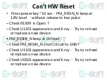
Page 32: ...Can t HW Reset ...

Page 33: ...heck R1309 is Open Check U1101 appearance and X ray Try to re heat or replace a new device PM_RESIN_N keep at 0V level Check PM_RESIN_N short circuit to GND Check U1101 appearance and X ray Try to re heat or replace a new device Check U0501 appearance and X ray Try to re heat or replace a new device ...

Page 34: ...USB Can t Work ...

Page 35: ...S_DP and TP_1005 USB_HS_DM and TP_1006 very close to short circuit Check FL1000 TP1007 USB_PWR without 5V Check usb cable function Oaky Check J1000 bad connection with cable Check C1011 R1013 C1001 D1000 short circuit toGND ...

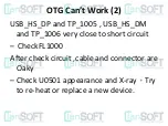
Page 36: ...USB Can t Work 2 After check circuit cable and connector are oaky Check U0501 appearance and X ray try to re heat or replace a new device ...

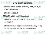
Page 37: ...OTG Can t Work ...

Page 38: ... Work 1 Connect OTG SLAVE Device PM_USB_ID Can t Hi Low Check J1000 4 TP1007 with out 5V output Check C1011 R1013 C1001 D1000 short to GND Check U0501 appearance and X ray Try to re heat or replace a new device ...

Page 39: ...Work 2 USB_HS_DP and TP_1005 USB_HS_DM and TP_1006 very close to short circuit CheckFL1000 After check circuit cable and connector are Oaky Check U0501 appearance and X ray Try to re heat or replace a new device ...

Page 40: ...Touch Panel Can t Work ...

Page 41: ...n t Work 1 Check Touch Panel and Touch connector are corrected connected VREG_LVS1_1P8V without 1 8V Check U1101 VREG_L19_2P85V without 2 8V Check U1101 TP12003 TS_RST_N keep at LOW Check TS_RST_N short to GND ...

Page 42: ...Touch Can t Work 2 TS_ID is 1 8V Check R10026 Keep press Touch Panel TS_INT_N should be High Low pulse Check R11004 TS_I2C_SCL TS_I2C_SDA without I2C data clock waveform Check R0703 R0704 ...

Page 43: ...Sub Camera Abnormal ...

Page 44: ...Sub Camera Abnormal 1 Power supply 5M_DVDD_1V2 without 1 2V Check U1101 B12002 C12002 5M_CAM_AVDD without 2 8V Check U1101 C12006 5M_VDDIO_1V8 without 1 8V Check U1101 C12004 B12001 ...

Page 45: ...Camera Abnormal 2 Control Signal CAM1_RST_N keep at LOW Check U0501 CAM_I2C_SDA CAM_I2C_SCK keep at LOW Check U1001 CAM_I2C_SDA CAM_I2C_SCK Keep at HIGH but without I2C Clock Data waveform Check R0705 R0706 ...

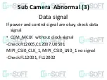
Page 46: ... Camera Abnormal 3 Data signal If power and control signal are okay check data signal CCM_MCLK without clock signal Check R12005 C12007 U0501 MIPI_CSI0_CLK_1 MIPI_CSI0_LN0_1 no signal Check FL12001 FL12002 ...

Page 47: ...Main Camera Abnormal ...

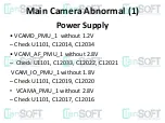
Page 48: ...ower Supply VCAMD_PMU_1 without 1 2V Check U1101 C12014 C12034 VCAM_AF_PMU_1 without 2 8V Check U1101 C12033 C12022 C12021 VCAM_IO_PMU_1 without 1 8V Check U1101 C12019 C12020 VCAMA_PMU_1 without 2 8V Check U1101 C12017 C12016 ...

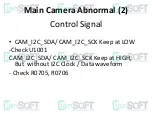
Page 49: ...Main Camera Abnormal 2 Control Signal CAM_I2C_SDA CAM_I2C_SCK Keep at LOW Check U1001 CAM_I2C_SDA CAM_I2C_SCK Keep at HIGH But without I2C Clock Data waveform Check R0705 R0706 ...

Page 50: ...ra Abnormal 3 Data Signal If power and control signal are Okay check data signal CAM_MCLK_13M without clock signal Check R12030 U0501 MDN1 4 MDP1 4 MCP MCN no signal Check FL12007 FL12008 FL12009 F12010 FL12011 ...

Page 51: ...Main MICROPHONE Abnormal ...

Page 52: ...Main MIC Abnormal 1 MIC_BIAS1_Main without 1 8V Check L899 C826 U1001 Blow air flow to mic device MIC1_P_1 MIC1_M_1 no signal Check mic device and L815 C825 PMIC_AUDIO_REF_CLK no signal Check R410 U0501 ...

Page 53: ...Sub MICROPHONE Abnormal ...

Page 54: ...b MIC Abnormal 1 MIC_BIAS1_Sub without 1 8V Check L808 C820 U1001 Blow air flow to mic device MIC3_P_1 MIC3_M_1 no signal Check mic device and U800 L812 C819 PMIC_AUDIO_REF_CLK no signal Check R410 U0501 ...

Page 55: ...E Compass Abnormal ...

Page 56: ...k U1397 G Sensor power and signal are Oaky VREG_L19_2P85 without 2 8V Check U1101 Check U1397 Short circuit VREG_LVS4_1P8 without 1 8V Check U1101 Check U1101 short circuit I2C Data CLK pin Short to GND Check R0701 R702 U0501 ...

Page 57: ...Volume Key Abnormal ...

Page 58: ...new SUB PCBA to Check function VOL_UP_KEY with 1 8V but press Rear key vol up key can t change to low Check J1401 VOL_UP_KEY is floating Multimeter check is 0 6V Oscilloscope check is 0V Check U0501 VOL_UP_KEY short circuit to GND Check J1401 Check U0501 ...

Page 59: ...RESIN_N is 1 8V But pressRear key vol down key can t change low Check J1401 PM_RESIN_N is floating Multimeter check is 0 6V Oscilloscope check is 0V CheckU0501 PM_RESIN_N Short circuit to GND Check J1401 Check U1101 Check U0501 ...

Page 60: ...Vibrator Abnormal ...

Page 61: ...ge Check D813 C829 Press home key PM_VIB_DRV_N Can t change to 1 2V Check J4203 Remove D813 C829 Symptom the same Check U1101 PM_VIB_DRV_N can reach VPH_PWR s voltage PM_VIB_DRV_N can change to1 2V But vibrator still can t work Change a new vibrator device ...

Page 62: ...eMMC Check if R610 pin2 is 2 95V or not Check if Dual_VCCQ_eMMC at R1601 pin2 is 1 8V or not Check that SDC1_eMMC_CLK is 52Mhz and SDC1_eMMC_CMD SDC1_eMMC_D0 are the high low transition signals ...

Page 63: ...if VREG_L22 VREG_L23 is 2 85V 1 8V or not Check if UIM1_RESET UIM2_RESET is 2 85V 1 8V or not UIM1_DET UIM2_DET is H when the SIM card is inserted Check if UIM1_CLK is 3 84Mhz and UIM1_DATA is a high low transition signal ...

Page 64: ...6 pin2 is 2 85V or not Check if R1397 pin2 shall is 1 8V or not Check if SENSORS_I2C_SCL R702 pin1 is 400Khz and SENSORS_I2C_SDA R0701 pin1 is a high low transition signal Check if TP6302 ACCL_INT_N is low when the sensor actives ...

Page 65: ...t Check if R1399 pin2 is 2 85V or not Check if R1398 pin2 is 1 8V or not Check if SENSORS_I2C_SCL R702 pin1 is 400Khz and SENSORS_I2C_SDA R0701 pin1 is a high low transition signal Check if R1398 pin1 PROXIMITY_INT_N is low or not when the object is close the sensor ...

Page 66: ... 8 Ohm Check C700 pin1 is above 3 4V or not Check C709 pin1 is above 3 4V or not Removed speaker and playing sound then checking if C711 pin1 is sort of square ware or not If the audio signals can t be measured on C711 pin1 and C710 pin1 please check the U700 ...

Page 67: ...DTV test I Check if R16001 pin2 VPH_PWR is above 3 4V or not Check if R3537 pin1 DTV_1V8_EN_N is 1 8V or not Check if C3539 pin1 DTV_1P1V is 1 1V or not Check if C3538 pin1 DTV_1P8V is 1 8V or not ...

Page 68: ... R3520 pin2 DTV_RESET_N is 1 8V or not Check if C3517 pin1 VDDPLL is activated or not Check if C3520 pin1 VDDLDO is activated or low Check if C3523 pin1 VDDLRF is activated or low Check if C3528 pin1 VDDLRF is 2 05V or not ...

Page 69: ...Thank you ...

Reviews: