


4-46
Chapter 4: BIOS setup
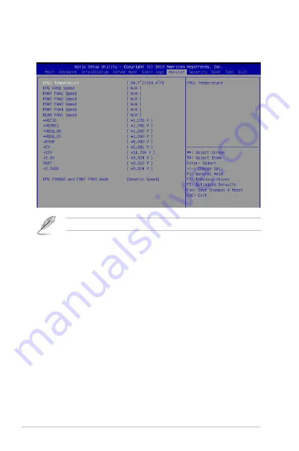
4.8
Monitor menu
The Monitor menu displays the system temperature/power status, and allows you to change
the fan settings.
Scroll down to view the other items
CPU1 Temperature [xxx°C/xxx°F]
The onboard hardware monitor automatically detects and displays the CPU
temperatures.
CPU FAN1 Speed; FRNT FAN1–4 Speed; REAR FAN1 Speed [xxxx RPM] or
[N/A]
The onboard hardware monitor automatically detects and displays the speed of CPU fans,
front fans, and rear fan in rotations per minute (RPM). If the fan is not connected to the
motherboard, the field shows N/A.
+VCCIO Voltage, VCORE1 Voltage, +VDDQ_AB Voltage, +VDDQ_CD Voltage,
+5VSB Voltage, +5V Voltage, +12V Voltage, +3.3V Voltage, VBAT Voltage,
+3.3VSB Voltage
The onboard hardware monitor automatically detects the voltage output through the onboard
voltage regulators.
CPU FAN1&2 and FRNT FAN1 mode [Generic Speed]
Allows you to configure the ASUS Smart Fan feature that smartly adjusts the fan speeds for
more efficient system operation.
Configuration options: [Generic Speed] [High Speed Speed] [Full Speed Speed] [Manual]
Duty % [50]
This item appears only when CPU FAN1&2 and FRNT FAN1 mode is set to [Manual].
This item allows you to configure the fan duty setting from 10% to 100%.
Summary of Contents for Z10PA-U8
Page 1: ...Z10PA U8 Series User Guide ...
Page 22: ...2 4 Chapter 2 Hardware information 2 2 3 Motherboard layout Z10PA U8 10G 2S ...
Page 23: ...2 5 Z10PA U8 Series Z10PA U8 ...
Page 56: ...2 38 Chapter 2 Hardware information ...
Page 60: ...3 4 Chapter 3 Powering up ...
Page 114: ...4 54 Chapter 4 BIOS setup ...
Page 152: ...5 38 Chapter 5 RAID configuration ...
Page 180: ...A 2 Appendix A Reference information A 1 Z10PA U8 Series block diagram Z10PA U8 10G 2S ...
Page 181: ...Z10PA U8 Series A 3 Z10PA U8 ...