


5-23
ASUS T3-P5945GC
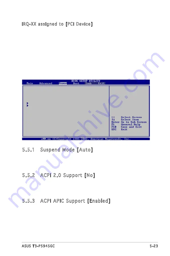
5.5
Power menu
The Power menu items allow you to change the settings for the ACPI and
Advanced Power Management (APM). Select an item then press <Enter> to
display the configuration options.
5.5.1 Suspend Mode [Auto]
Allows you to select the Advanced Configuration and Power Interface
(ACPI) state to be used for system suspend.
Configuration options: [S1 (POS) Only] [S3 Only] [Auto]
5.5.2 ACPI 2.0 Support [No]
Allows you to add more tables for Advanced Configuration and Power
Interface (ACPI) 2.0 specifications.
Configuration options: [No] [Yes]
5.5.3 ACPI APIC Support [Enabled]
Allows you to enable or disable the Advanced Configuration and Power
Interface (ACPI) support in the Advanced Programmable Interrupt Controller
(APIC). When set to Enabled, the ACPI APIC table pointer is included in the
RSDT pointer list. Configuration options: [Disabled] [Enabled]
Suspend Mode
[Auto]
ACPI 2.0 Support
[No]
ACPI APIC Support
[Enabled]
APM Configuration
Hardware Monitor
IRQ-XX assigned to [PCI Device]
When set to [PCI Device], the specific IRQ is free for use of PCI/PnP
devices. When set to [Reserved], the IRQ is reserved for legacy ISA
devices. Configuration options: [PCI Device] [Reserved]


