


C h a p t e r 1 : P r o d u c t i n t r o d u c t i o n
C h a p t e r 1 : P r o d u c t i n t r o d u c t i o n
C h a p t e r 1 : P r o d u c t i n t r o d u c t i o n
C h a p t e r 1 : P r o d u c t i n t r o d u c t i o n
C h a p t e r 1 : P r o d u c t i n t r o d u c t i o n
1 - 6
1 - 6
1 - 6
1 - 6
1 - 6
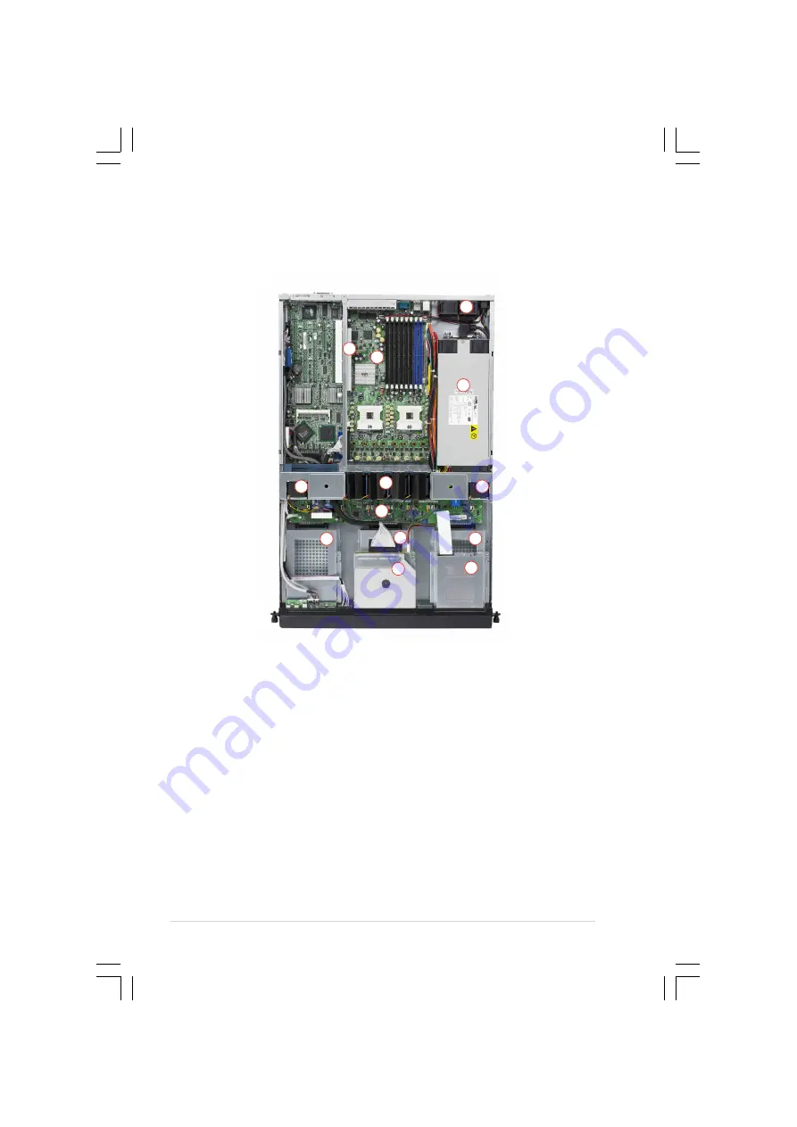
1.6
Internal features
The barebone server includes the basic components as shown.
1.
PCI-X riser card bracket
2.
Rear fans
3.
ASUS NCL-DSR1 motherboard
4.
Power supply
5.
Device fan
6.
System fans (8 fans)
7.
Device fan
8.
SCSI backplane
9.
Hot-swap HDD tray 1
10. Hot-swap HDD tray 2
11. Hot-swap HDD tray 3
12. Slim optical drive
13. Slim floppy drive
1
4
3
2
7
6
5
8
9
11
10
13
12