ROG MAXIMUS XII HERO (WI-FI)
A-3
Ap
pendix
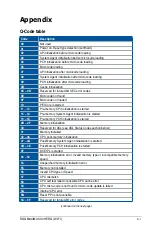
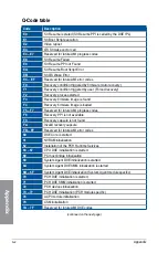
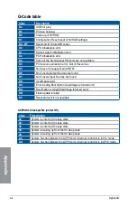
Q-Code table
Code
Description
90
Boot Device Selection (BDS) phase is started
91
Driver connecting is started
92
PCI Bus initialization is started
93
PCI Bus Hot Plug Controller Initialization
94
PCI Bus Enumeration
95
PCI Bus Request Resources
96
PCI Bus Assign Resources
97
Console Output devices connect
98
Console input devices connect
99
Super IO Initialization
9A
USB initialization is started
9B
USB Reset
9C
USB Detect
9D
USB Enable
9E – 9F
Reserved for future AMI codes
A0
IDE initialization is started
A1
IDE Reset
A2
IDE Detect
A3
IDE Enable
A4
SCSI initialization is started
A5
SCSI Reset
A6
SCSI Detect
A7
SCSI Enable
A8
Setup Verifying Password
A9
Start of Setup
AA
Reserved for ASL (see ASL Status Codes section below)
AB
Setup Input Wait
AC
Reserved for ASL (see ASL Status Codes section below)
AD
Ready To Boot event
AE
Legacy Boot event
AF
Exit Boot Services event
B0
Runtime Set Virtual Address MAP Begin
B1
Runtime Set Virtual Address MAP End
B2
Legacy Option ROM Initialization
B3
System Reset
(continued on the next page)
Summary of Contents for ROG MAXIMUS XII HERO WI-FI
Page 1: ...Motherboard ROG MAXIMUS XII HERO WI FI ...
Page 4: ...iv Appendix Q Code table A 1 Notices A 5 ASUS contact information A 12 ...
Page 16: ...xvi ...
Page 18: ...1 2 Chapter 1 Product Introduction Chapter 1 1 2 Motherboard layout ...
Page 44: ...2 2 Chapter 2 Basic Installation Chapter 2 ...
Page 47: ...ROG MAXIMUS XII HERO WI FI 2 5 Chapter 2 2 1 3 DIMM installation To remove a DIMM ...
Page 53: ...ROG MAXIMUS XII HERO WI FI 2 11 Chapter 2 2 1 8 SATA device connection OR ...
Page 64: ...2 22 Chapter 2 Basic Installation Chapter 2 ...


