ROG MAXIMUS XII HERO (WI-FI)
1-21
Chapter 1
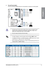
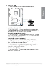
18. System Panel header
The System Panel header supports several chassis-mounted functions.
•
System Power LED header (PLED)
The 2-pin header allows you to connect the System Power LED. The System Power
LED lights up when the system is connected to a power source, or when you turn on
the system power, and blinks when the system is in sleep mode.
•
Storage Device Activity LED header (HDLED)
The 2-pin header allows you to connect the Storage Device Activity LED. The Storage
Device Activity LED lights up or blinks when data is read from or written to the storage
device or storage device add-on card.
•
System Warning Speaker header (SPEAKER)
The 4-pin header allows you to connect the chassis-mounted system warning
speaker. The speaker allows you to hear system beeps and warnings.
•
Power Button/Soft-off Button header (PWRBTN)
The 3-1 pin header allows you to connect the system power button. Press the
power button to power up the system, or put the system into sleep or soft-off mode
(depending on the operating system settings).
•
Reset button header (RESET)
The 2-pin header allows you to connect the chassis-mounted reset button. Press the
reset button to reboot the system.
Summary of Contents for ROG MAXIMUS XII HERO WI-FI
Page 1: ...Motherboard ROG MAXIMUS XII HERO WI FI ...
Page 4: ...iv Appendix Q Code table A 1 Notices A 5 ASUS contact information A 12 ...
Page 16: ...xvi ...
Page 18: ...1 2 Chapter 1 Product Introduction Chapter 1 1 2 Motherboard layout ...
Page 44: ...2 2 Chapter 2 Basic Installation Chapter 2 ...
Page 47: ...ROG MAXIMUS XII HERO WI FI 2 5 Chapter 2 2 1 3 DIMM installation To remove a DIMM ...
Page 53: ...ROG MAXIMUS XII HERO WI FI 2 11 Chapter 2 2 1 8 SATA device connection OR ...
Page 64: ...2 22 Chapter 2 Basic Installation Chapter 2 ...


