background image

ROG RAMPAGE IV GENE

5-7

Chapter 5

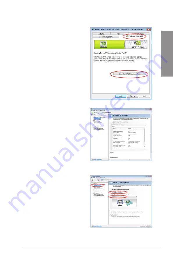
B4.  Select the NVIDIA GeForce tab, and 

then click 

Start the NVIDIA Control 

Panel

.

B5.  The NVIDIA Control Panel window 

appears.

Enabling SLI settings

From the NVIDIA Control Panel window, select 

Set SLI Configuration

. Click 

Enable SLI


and set the display for viewing SLI rendered 

content. When done, click 

Apply

.

Summary of Contents for Rampage IV GENE

Page 1: ...Motherboard RAMPAGE IV GENE ...

Page 2: ...planation and to the owners benefit without intent to infringe Offer to Provide Source Code of Certain Software This product may contain copyrighted software that is licensed under the General Public License GPL and under the Lesser General Public License Version LGPL The GPL and LGPL licensed code in this product is distributed without any warranty Copies of these licenses are included in this pr...

Page 3: ... Processing Unit CPU 2 4 2 2 3 System memory 2 5 2 2 4 Expansion slots 2 11 2 2 5 Onboard switches 2 13 2 2 6 Onboard LEDs 2 15 2 2 7 Internal connectors 2 22 2 3 Building your computer system 2 32 2 3 1 Additional tools and components to build a PC system 2 32 2 3 2 CPU installation 2 33 2 3 3 CPU heatsink and fan assembly installation 2 35 2 3 4 DIMM installation 2 37 2 3 5 Motherboard installat...

Page 4: ...ration 3 27 3 5 6 Onboard Devices Configuraton 3 28 3 5 7 APM 3 30 3 6 Monitor menu 3 31 3 7 Boot menu 3 34 3 8 Tools menu 3 36 3 8 1 ASUS EZ Flash 2 Utility 3 36 3 8 2 ASUS SPD Information 3 37 3 8 3 ASUS O C Profile 3 38 3 8 4 GO Button File 3 39 3 9 Exit menu 3 40 3 10 Updating BIOS 3 41 3 10 1 ASUS Update utility 3 41 3 10 2 ASUS EZ Flash 2 Utility 3 45 3 10 3 ASUS CrashFree BIOS 3 utility 3 4...

Page 5: ...on ROM utility 4 31 4 5 Creating a RAID driver disk 4 35 4 5 1 Creating a RAID driver disk without entering the OS 4 35 4 5 2 Creating a RAID driver disk in Windows 4 35 4 5 3 Installing the RAID driver during Windows OS installation 4 36 4 5 4 Using a USB floppy disk drive 4 37 Chapter 5 Multiple GPU technology support 5 1 AMD CrossFireX technology 5 1 5 1 1 Requirements 5 1 5 1 2 Before you begi...

Page 6: ...he dealer or an experienced radio TV technician for help The use of shielded cables for connection of the monitor to the graphics card is required to assure compliance with FCC regulations Changes or modifications to this unit not expressly approved by the party responsible for compliance could void the user s authority to operate this equipment FCC Radio Frequency RF Exposure Caution Statement An...

Page 7: ...9 1 EN 301 489 17 Effective use of the radio spectrum as in Article 3 2 Radio test suites according to EN 300 328 2 CE Mark Warning CE marking for devices without wireless LAN Bluetooth The shipped version of this device complies with the requirements of the EEC directives 2004 108 EC Electromagnetic compatibility and 2006 95 EC Low voltage directive CE marking for devices with wireless LAN Blueto...

Page 8: ...property is not permitted In the departments listed below for the entire 2 4 GHz band Maximum authorized power indoors is 100mW Maximum authorized power outdoors is 10mW Departments in which the use of the 2400 2483 5 MHz band is permitted with an EIRP of less than 100mW indoors and less than 10mW outdoors 01 Ain 02 Aisne 03 Allier 05 Hautes Alpes 08 Ardennes 09 Ariège 11 Aude 12 Aveyron 16 Charen...

Page 9: ...ing RF exposure compliance Operation is subject to the following two conditions This device may not cause interference and This device must accept any interference including interference that may cause undesired operation of the device To prevent radio interference to the licensed service i e co channel Mobile Satellite systems this device is intended to be operated indoors and away from windows t...

Page 10: ...et to the correct voltage in your area If you are not sure about the voltage of the electrical outlet you are using contact your local power company If the power supply is broken do not try to fix it by yourself Contact a qualified service technician or your retailer The optical S PDIF is an optional component may or may not be included in your motherboard and is defined as a CLASS 1 LASER PRODUCT...

Page 11: ...ce If you encounter technical problems with the product contact a qualified service technician or your retailer DO NOT throw the motherboard in municipal waste This product has been designed to enable proper reuse of parts and recycling This symbol of the crossed out wheeled bin indicates that the product electrical and electronic equipment should not be placed in municipal waste Check local regul...

Page 12: ...e contains the following parts Chapter 1 Product introduction This chapter describes the features of the motherboard and the new technology it supports Chapter 2 Hardware information This chapter lists the hardware setup procedures that you have to perform when installing system components It includes description of the switches jumpers and connectors on the motherboard Chapter 3 BIOS setup This c...

Page 13: ...symbols used throughout this manual Typography Bold text Indicates a menu or an item to select Italics Used to emphasize a word or a phrase Key Keys enclosed in the less than and greater than sign means that you must press the enclosed key Example Enter means that you must press the Enter or Return key Key1 Key2 Key3 If you must press two or more keys simultaneously the key names are linked with a...

Page 14: ...ports x8 mode 1 x PCIe2 0 x4 slot x4 mode Multi GPU Technology Supports NVIDIA SLI AMD CrossFireX Technology Storage Intel X79 Express Chipset built in 2 x SATA 6Gb s ports red with RAID 0 1 5 10 support 3 x SATA 3Gb s ports black with RAID 0 1 5 10 support 1 x External SATA 3 Gb s port at rear SATA on the Go ASM1061 controller 2 x SATA 6Gb s ports red These SATA ports are for data hard drives onl...

Page 15: ... Engine Digi II 8 phase CPU power 3 phase VCCSA power 2 2 phase DRAM power USB BIOS Flashback ROG Connect Mem TweakIt ROG GameFirst MemOK ProbeIt Extreme Tweaker CPU Level Up iROG Loadline Calibration UEFI BIOS features ROG BIOS Print GPU DIMM Post Intelligent overclocking tools ASUS TurboV EVO O C Profile Overclocking Protection COP EX Component Overheat Protection EX ASUS C P R CPU Parameter Rec...

Page 16: ... can be switched to ROG Connect white 2 x USB 3 0 2 0 ports blue 1 x LAN RJ45 port 1 x 8 channel Audio I O 1 x External SATA port Internal I O Connectors 1 x USB 3 0 connector red supports additional 2 USB 3 0 ports 2 x USB 2 0 connectors support additional 4 USB 2 0 ports 4 x SATA 6Gb s connectors red 3 x SATA 3Gb s connectors black Debug LED 5 x Fan connectors 2 x CPU 3 x Chassis 11 x Probelt me...

Page 17: ...ions ASUS AI Suite II ROG CPU Z ROG GameFirst Utility Sound Blaster X Fi MB2 Utility ROG Mem TweakIt Utility ROG Theme ASUS AI Charger WinZip ASUS USB 3 0 Boost ASUS WebStorage DAEMON Tools Pro Standard Kaspersky Anti Virus 1 year license Form Factor mATX Form Factor 9 6 inch x 9 6 inch 24 4cm x 24 4cm Specifications are subject to change without notice RAMPAGE IV GENE specifications summary ...

Page 18: ...xviii ...

Page 19: ...ge with the list below Chapter 1 Product introduction Chapter 1 1 2 Package contents Check your motherboard package for the following items Motherboard ROG RAMPAGE IV GENE Accessories 1 x ROG connect cable 1 x 2 in 1 ASUS Q Connector Kit 2 x 2 in 1 SATA 6Gb s signal cables 1 x 2 in 1 SATA 3Gb s signal cables 1 x SLI cable 1 x ROG theme label 1 x 12 in 1 ROG cable label 1 x I O Shield Application D...

Page 20: ...new socket 2011 Intel Core i7 Extreme Edition processors It improves performance by utilizing serial point to point links allowing for increased bandwidth and stability Additionally the X79 comes with 2 SATA 6Gb s and 4 SATA 3Gb s ports for faster data retrieval doubling the bandwidth of current bus systems PCIe 3 0 Ready The PCI Express 3 0 PCIe 3 0 is the latest PCI Express bus standard with imp...

Page 21: ...nnect ROG Connect links your main system to a notebook through a USB cable allowing you to view real time POST code and hardware status readouts on your notebook as well as make on the fly parameter adjustments at a purely hardware level ROG GameFirst The speed you need to pwn Low Internet latency allows you to frag more and get fragged less That s why ROG has introduced GameFirst a feature that m...

Page 22: ...o need to enter the BIOS or the operating system just plug the thumb drive into the ROG Connect port push the ROG Connect button for 2 seconds BIOS would be automatically flashed under standby power It s no doubt that USB BIOS Flashback gives overclockers the ultimate convenience CPU Level Up A simple click for an instant upgrade Wishing that you could have a more expensive CPU Upgrade your CPU at...

Page 23: ...ble to determine fail safe settings that can improve the system booting Onboard Switch No more shorting pins or moving jumpers With an easy press during an overclock this exclusive onboard switch allows the gamer to effortlessly fine tune the performance without having to shorten the pins or moving the jumpers ASUS Q Connector Making the connections quick and accurate The Q Connector allows you to...

Page 24: ...und Blaster X Fi MB2 suite the SupremeFX III is the perfect choice to provide an exceptional gaming experience with realistic sound effects 1 3 4 ASUS Special Features USB 3 0 Support 10X Front Rear true USB 3 0 support Experience ultra fast data transfers at 4 8Gbps with USB 3 0 the latest connectivity standard Built to connect easily with next generation components and peripherals USB 3 0 transf...

Page 25: ... multiple BIOS settings Freely share and distribute your favorite overclocking settings The motherboard features the ASUS O C Profile that allows users to conveniently store or load multiple BIOS settings The BIOS settings can be stored in the CMOS or a separate file giving users the freedom to share and distribute their favorite overclocking settings Q Shield Easy and comfortable installations Th...

Page 26: ...est ROG CPU Z Whole new design of CPU Z ROG CPU Z is a customized ROG version authorized by CPUID It has the same functionality and credibility as the original version with a unique design Use the whole new look of ROG CPU Z to truly report your CPU related information and your uniqueness DAEMON Tools Pro Standard The real tool for optical and virtual discs DAEMON Tools Pro offers essential functi...

Page 27: ...object such as the power supply case to avoid damaging them due to static electricity Hold components by the edges to avoid touching the ICs on them Whenever you uninstall any component place it on a grounded antistatic pad or in the bag that came with the component Before you install or remove any component ensure that the ATX power supply is switched off or the power cord is detached from the po...

Page 28: ...dware information Chapter 2 Refer to 2 2 8 Internal connectors and 2 3 10 Rear panel connection for more information about rear panel connectors and internal connectors 2 2 Motherboard overview 2 2 1 Motherboard layout ...

Page 29: ...ATXPWR 2 29 7 USB 3 0 connector 20 1 pin USB3_34 2 25 8 Intel X79 Serial ATA 3Gb s connectors 7 pin SATA3G_1 3 black 2 23 9 Intel X79 Serial ATA 6Gb s connectors 7 pin SATA6G_1 2 red 2 22 10 ASMedia Serial ATA 6Gb s connectors 7 pin SATA6G_E1 E2 red 2 24 11 System panel connector 20 8 pin PANEL 2 29 12 USB 2 0 connectors 10 1 pin USB910 USB1112 2 26 13 Go LED 2 16 14 Go Button 2 14 15 Reset switch...

Page 30: ...g or if you see any damage to the PnP cap socket contacts motherboard components ASUS will shoulder the cost of repair only if the damage is shipment transit related Keep the cap after installing the motherboard ASUS will process Return Merchandise Authorization RMA requests only if the motherboard comes with the cap on the LGA2011 socket The product warranty does not cover damage to the socket co...

Page 31: ...y configurations 2 2 3 System memory The motherboard comes with four Double Data Rate 3 DDR3 Dual Inline Memory Modules DIMM slots A DDR3 module is notched differently from a DDR or DDR2 module DO NOT install a DDR or DDR2 memory module to the DDR3 slot ...

Page 32: ...ory address limitation on 32 bit Windows OS when you install 4GB or more memory on the motherboard the actual usable memory for the OS can be about 3GB or less For effective use of memory we recommend that you do any of the following Use a maximum of 3GB system memory if you are using a 32 bit Windows OS Install a 64 bit Windows OS when you want to install 4GB or more on the motherboard For more d...

Page 33: ...1 9 27 1 65 G SKILL F3 19200CL9D 4GBPIS XMP 4G 2x2G DS 9 11 9 28 1 65 Transcend TX2400KLU 4GK 381850 XMP 2GB DS 1 65 Transcend TX2400KLU 4GK 374243 XMP 2GB DS 1 65 Vendors Part No Size SS DS Chip Brand Chip NO Timing Voltage DIMM socket support Optional 2 DIMM 3 DIMM 4 DIMM Apacer 78 BAGE4 AFD0C XMP 8GB 2x4GB DS 9 9 9 24 CORSAIR CMT4GX3M2A2133C9 XMP 4GB 2x2GB DS 9 10 9 24 1 65 CORSAIR CMT4GX3M2B21...

Page 34: ... 6GB 3x2GB DS 7 7 7 20 1 65 Vendors Part No Size SS DS Chip Brand Chip NO Timing Voltage DIMM socket support Optional 2 DIMM 3 DIMM 4 DIMM A DATA AX3U1866GC4G9B XMP 4GB DS 9 11 9 27 1 55 1 75 CORSAIR CMZ8GX3M2A1866C9 XMP 8GB 2x4GB DS 9 10 9 27 1 5 G SKILL F3 14900CL9Q 16GBXL XMP 16GB 4x4GB DS 9 10 9 28 1 5 G SKILL F3 15000CL9D 4GBTD XMP 4GB 2x2GB DS 9 9 9 24 1 65 G SKILL F3 14900CL9D 8GBSR XMP 8GB...

Page 35: ... 6 KINGMAX FLGD45F B8MF7 XMP 1GB SS KINGSTON KHX1600C9D3K3 12GX XMP 12GB 3x4GB DS 1 65 KINGSTON KHX1600C9D3K6 24GX XMP 24GB 6x4GB DS 9 1 65 KINGSTON KHX1600C8D3K2 4GX XMP 4GB 2x2GB DS 8 1 65 KINGSTON KHX1600C9D3K2 4GX XMP 4GB 2x2GB DS 1 65 KINGSTON KHX1600C9D3LK2 4GX XMP 4GB 2x2GB DS 1 65 KINGSTON KHX1600C9D3X2K2 4GX XMP 4GB 2x2GB DS 9 1 65 KINGSTON KHX1600C9D3K3 6GX XMP 6GB 3x2GB DS 9 1 65 KINGST...

Page 36: ...GB DS 8 8 8 21 1 5 KINGMAX FLFD45F B8KL9 1GB SS KINGMAX KFB8FNLXF BNF 15A KINGSTON KVR1333D3N9 2G 2GB DS Elpida J1108BDBG DJ F 1 5 MICRON MT16JTF51264AZ 1G4M1 4GB DS Micron IGM22 D9PFJ SAMSUNG M378B5673EH1 CH9 2GB DS SAMSUNG K4B1G0846E Elixir M2F2G64CB88G7N CG 2GB SS Elxir N2CB2G80GN CG Patriot PSD31G13332 1GB DS Patriot PM64M8D3BU 15 UMAX E41302GP0 73BDB 2GB DS UMAX U2S24D30TP 13 RAMPAGE IV GENE ...

Page 37: ...2 PCIe 2 0 x4_1 slot 3 PCIe 3 0 x16_2 slot 4 PCIe 3 0 x8_3 slot Refer to the following configuration table for installation Slot No Single VGA SLI CFX 1 x16 x16 3 x16 PCIe 3 0 x8_3 slot is always running at x8 mode We recommend that you provide sufficient power when running CrossFireX or SLI mode See page 2 30 for details Connect a chassis fan to the motherboard connector labeled CHA_FAN1 2 3 when...

Page 38: ...for this motherboard A B C D E F G H PCIE_X16_1 shared PCIE_X16_2 shared PCIE_X8_3 shared PCIE_X4 shared ASM USB3 1 shared ASM USB3 2 shared ASM SATA6 1 shared Intel W82579 shared EHCI 0 shared EHCI 1 shared High Definition Audio shared SATA 0 shared SATA 0 shared ...

Page 39: ...tune performance when working on a bare or open case system This is ideal for overclockers and gamers who continually change settings to enhance system performance 1 Power on switch Press the power on switch to wake power up the system 2 Reset switch Press the reset switch to reboot the system ...

Page 40: ...14 Chapter 2 Hardware information Chapter 2 3 GO button Press the GO button before POST to enable MemOK or press it to quickly load the preset profile GO_Button file for temporary overclocking when in OS ...

Page 41: ...ive activity and an onboard switch for power status For more information about voltage adjustment refer to 3 3 Extreme Tweaker menu 1 Hard Disk LED The hard disk LED is designed to indicate the hard disk activity It blinks when data is being written into or read from the hard disk drive The LED does not light up when there is no hard disk drive connected to the motherboard or when the hard disk dr...

Page 42: ...le GO_Button file for temporary overclocking when in OS 3 Q LED Q LEDs check key components CPU DRAM VGA card and booting devices in sequence during motherboard booting process If an error is found the corresponding LED will continue lighting until the problem is solved This user friendly design provides an intuitional way to locate the root problem within a second ...

Page 43: ...ff mode This is a reminder that you should shut down the system and unplug the power cable before removing or plugging in any motherboard component The illustration below shows the location of the onboard power on switch 5 Debug LEDs The Debug LED design provides you the 2 digit display allowing you to know the system status Refer to the Debug table below for details ...

Page 44: ...ocode loading 09 PCH initialization after microcode loading 0A OEM initialization after microcode loading 0B Cache initialization 0C 0D Reserved for future AMI SEC error codes 0E Microcode not found 0F Microcode not loaded 10 PEI Core is started 11 14 Pre memory CPU initialization is started 15 18 Pre memory System Agent initialization is started 19 1C Pre memory PCH initialization is started 1D 2...

Page 45: ...gress codes E8 S3 Resume Failed E9 S3 Resume PPI not Found EA S3 Resume Boot Script Error EB S3 OS Wake Error EC EF Reserved for future AMI error codes F0 Recovery condition triggered by firmware Auto recovery F1 Recovery condition triggered by user Forced recovery F2 Recovery process started F3 Recovery firmware image is found F4 Recovery firmware image is loaded F5 F7 Reserved for future AMI pro...

Page 46: ...us Assign Resources 97 Console Output devices connect 98 Console input devices connect 99 Super IO Initialization 9A USB initialization is started 9B USB Reset 9C USB Detect 9D USB Enable 9E 9F Reserved for future AMI codes A0 IDE initialization is started A1 IDE Reset A2 IDE Detect A3 IDE Enable A4 SCSI initialization is started A5 SCSI Reset A6 SCSI Detect A7 SCSI Enable A8 Setup Verifying Passw...

Page 47: ...D9 Error loading Boot Option LoadImage returned error DA Boot Option is failed StartImage returned error DB Flash update is failed DC Reset protocol is not available Debug table continued Status Code Description 01 System is entering S1 sleep state 02 System is entering S2 sleep state 03 System is entering S3 sleep state 04 System is entering S4 sleep state 05 System is entering S5 sleep state 10 ...

Page 48: ...e set to AHCI Mode by default If you intend to create a Serial ATA RAID set using these connectors set the SATA Mode item in the BIOS to RAID Mode Refer to section 3 5 4 SATA Configuration for details Before creating a RAID set refer to section 4 4 RAID configurations or the manual bundled in the motherboard support DVD When using NCQ set the SATA Mode in the BIOS to AHCI Mode Refer to section 3 5...

Page 49: ... to AHCI Mode by default If you intend to create a Serial ATA RAID set using these connectors set the SATA Mode item in the BIOS to RAID Mode Refer to section 3 5 4 SATA Configuration for details Before creating a RAID set refer to section 4 4 RAID configurations or the manual bundled in the motherboard support DVD When using NCQ set the SATA Mode in the BIOS to AHCI Mode Refer to section 3 5 4 SA...

Page 50: ...ves via Serial ATA 6 0 Gb s signal cables The SATA6G_E1 E2 red connectors are for data drives only ATAPI device is not supported You must install Windows XP Service Pack 3 or later versions before using Serial ATA hard disk drives When using NCQ set the ASM1061 Storage Controller item in the BIOS to Enabled Refer to section 3 5 6 Onboard Devices Configuration for details ...

Page 51: ... additional USB 3 0 ports and complies with the USB 3 0 specificaton that supports up to 4 8Gbps connection speed If the USB 3 0 front panel cable is available from your system chassis with this USB 3 0 connector you can have a front panel USB 3 0 solution The USB 3 0 module is purchased separately ...

Page 52: ...ver connect a 1394 cable to the USB connectors Doing so will damage the motherboard 5 USB 2 0 connectors 10 1 pin USB910 USB1112 These connectors are for USB 2 0 ports Connect the USB module cable to any of these connectors then install the module to a slot opening at the back of the system chassis These USB connectors comply with USB 2 0 specification that supports up to 480 Mbps connection speed...

Page 53: ... pin SPDIF_OUT This connector is for an additional Sony Philips Digital Interface S PDIF port Connect the S PDIF Out module cable to this connector then install the module to a slot opening at the back of the system chassis The S PDIF module is purchased separately ...

Page 54: ...onnector The CPU_FAN connector supports the CPU fan of maximum 1A 12 W fan power If you install two VGA cards we recommend that you plug the rear chassis fan cable to the motherboard connector labeled CHA_FAN1 CHA_FAN2 or CHA_FAN3 for better thermal environment Do not forget to connect the fan cables to the fan connectors Insufficient air flow inside the system may damage the motherboard component...

Page 55: ...he motherboard s high definition audio capability If you want to connect a high definition front panel audio module to this connector set the Front Panel Type item in the BIOS setup to HD if you want to connect an AC 97 front panel audio module to this connector set the item to AC97 By default this connector is set to HD 9 ATX power connectors 24 pin EATXPWR 8 pin EATX12V These connectors are for ...

Page 56: ... Gigabyte P610A C1 AcBel API5PC36 GoldenField ATX S398 AcBel PC6018 GoldenField ATX S550 AMA AA1200U C GreatWall BTX 600SE AMA AA1000U C HECHUAN ST ATX330 Antec SG 850 Huntkey R85 Antec EA 380 Huntkey 磐石500 ASUS P 50GA I cute AP 600S ASUS P 55GA In Win COMMANDER IRP COM1500 ASUS U 65GA OCZ 1000PXS ASUS U 75HA OCZ 780MXS Be quiet BN073 SAMA YUHUI 350P Be quiet BN077 Seasonic SS 500GB Be quiet P6 PR...

Page 57: ...warning speaker 4 pin SPEAKER This 4 pin connector is for the chassis mounted system warning speaker The speaker allows you to hear system beeps and warnings ATX power button soft off button 2 pin PWRSW This connector is for the system power button Pressing the power button turns the system on or puts the system in sleep or soft off mode depending on the BIOS settings Pressing the power switch for...

Page 58: ...onents to build a PC system 1 bag of screws Philips cross screwdriver PC chassis Power supply unit Intel LGA 2011 CPU Intel LGA 2011 compatible CPU Fan DIMM SATA hard disk drive SATA optical disc drive optional Graphics card The tools and components in the table above are not included in the motherboard package ...

Page 59: ...r in opening closing the double latch Follow the instructions printed on the metal sealing hatch or the illustrations shown below in this manual The plastic cap will pop up automatically once the CPU is in place and the hatch properly sealed down 1 2 B A Load lever C B A B A 3 4 ...

Page 60: ...2 34 Chapter 2 Hardware information Chapter 2 B A 9 B A 7 8 Triangle mark 5 6 ...

Page 61: ...pter 2 2 3 3 CPU heatsink and fan assembly installation Apply the Thermal Interface Material to the CPU heatsink and CPU before you install the heatsink and fan if necessary To install the CPU heatsink and fan assembly 1 2 A B B A ...

Page 62: ...2 36 Chapter 2 Hardware information Chapter 2 To replace the LGA2011 CPU pad X Socket 1 2 3 4 5 ...

Page 63: ...ROG RAMPAGE IV GENE 2 37 Chapter 2 1 2 3 To remove a DIMM 2 3 4 DIMM installation B A ...

Page 64: ...ter 2 Hardware information Chapter 2 2 3 5 Motherboard installation The diagrams in this section are for reference only The motherboard layout may vary with models but the installation steps remain the same 1 2 ...

Page 65: ...ROG RAMPAGE IV GENE 2 39 Chapter 2 DO NOT overtighten the screws Doing so can damage the motherboard 3 ...

Page 66: ...2 40 Chapter 2 Hardware information Chapter 2 2 3 6 ATX Power connection 1 2 OR OR ...

Page 67: ...ROG RAMPAGE IV GENE 2 41 Chapter 2 2 3 7 SATA device connection OR 2 OR 1 ...

Page 68: ... 2 2 3 8 Front I O Connector IDE_LED POWER SW RESET SW IDE_LED IDE_LED PWR Reset Ground Ground 1 2 To install ASUS Q Connector USB 2 0 AAFP To install USB 2 0 Connector To install front panel audio connector USB 3 0 To install USB 3 0 Connector ...

Page 69: ...ROG RAMPAGE IV GENE 2 43 Chapter 2 2 3 9 Expansion Card installation To install PCIe x16 cards ...

Page 70: ... port 2 USB 2 0 ports the white port is also for ROG Connect 3 LAN RJ 45 port 4 External SATA port 5 USB 2 0 ports 6 Clear CMOS switch 7 Optical S PDIF out port 8 ROG Connect switch 9 USB 2 0 ports 10 USB 3 0 ports blue 11 Audio I O ports and Refer to the tables on the next page for LAN port LED and audio port definitions ...

Page 71: ...ntroller limitation USB 3 0 devices can only be used under Windows OS environment and after the USB 3 0 driver installation USB 3 0 devices can only be used as data storage only We strongly recommend that you connect USB 3 0 devices to USB 3 0 ports for faster and better performance for your USB 3 0 devices Audio 2 4 6 or 8 channel configuration Port H e a d s e t 2 channel 4 channel 6 channel 8 c...

Page 72: ...2 46 Chapter 2 Hardware information Chapter 2 2 3 11 Audio I O connections Audio I O ports Connect to Headphone and Mic Connect to Stereo Speakers Connect to 2 1 channel Speakers ...

Page 73: ...ROG RAMPAGE IV GENE 2 47 Chapter 2 Connect to 4 1 channel Speakers Connect to 5 1 channel Speakers Connect to 7 1 channel Speakers ...

Page 74: ... tests or POST While the tests are running the BIOS beeps refer to the BIOS beep codes table below or additional messages appear on the screen If you do not see anything within 30 seconds from the time you turned on the power the system may have failed a power on test Check the jumper settings and connections or call your retailer for assistance 7 At power on hold down the Delete key to enter the ...

Page 75: ...item modification When you start up the computer the system provides you with the opportunity to run this program Press Del during the Power On Self Test POST to enter the Setup utility Otherwise POST continues with its test routines If you wish to enter Setup after POST press Ctrl Alt Delete or press the reset button on the system chassis to restart the system You can also turn the system off and...

Page 76: ...ar on top of the screen has the following main items Extreme Tweaker For changing the overclocking settings Main For changing the basic system configuration Advanced For changing the advanced system settings Monitor For displaying the system temperature power status and changing the fan settings Boot For changing the system boot configuration Tool For configuring options for special functions Exit...

Page 77: ...onfiguration options for that item Scroll bar A scroll bar appears on the right side of a menu screen when there are items that do not fit on the screen Press the Up Down arrow keys or Page Up Page Down keys to display the other items on the screen Navigation keys At the bottom right corner of the menu screen are the navigation keys for the BIOS setup program Use the navigation keys to select item...

Page 78: ...vary depending on the devices you installed to the system The Boot Menu F8 button is available only when the boot device is installed to the system Normal mode ASUS Optimal mode Loads optimized default Displays the system properties of the selected mode on the right hand side Exits the BIOS setup program without saving the changes saves the changes and resets the system or enters the Advanced Mode...

Page 79: ...erclocking related items Be cautious when changing the settings of the Extreme Tweaker menu items Incorrect field values can cause the system to malfunction The configuration options for this section vary depending on the CPU and DIMM model you installed on the motherboard Scroll down to display the following items ...

Page 80: ...me overclocking and sources current into the processor in a bid to squeeze more frequency from it Ai Overclock Tuner Auto Allows you to select the CPU overclocking options to achieve the desired CPU internal frequency Select any of these preset overclocking configuration options Auto Loads the optimal settings for the system Manual Allows you to individually set overclocking parameters X M P The B...

Page 81: ...DDR3 1066MHz DDR3 1333MHz DDR3 1600MHz DDR3 1866MHz DDR3 2133MHz DDR3 2400MHz DDR3 2666MHz Selecting a very high memory frequency may cause the system to become unstable If this happens revert to the default setting Xtreme Tweaking Disabled This item may help improve some benchmarks performance Configuration options Disabled Enabled EPU Power Saving Mode Disabled Allows you to enable or disable th...

Page 82: ...electing Yes Rampage Tweak Auto Mode 1 can help Memory Compatibility Mode 2 can help overclocking and performance Configuration options Auto Mode 1 Mode 2 Primary Timings DRAM CAS Latency Auto Configuration options Auto 3 DRAM Clock 15 DRAM Clock DRAM RAS to CAS Delay Auto Configuration options Auto 4 DRAM Clock 15 DRAM Clock DRAM RAS PRE Time Auto Configuration options Auto 4 DRAM Clock 15 DRAM C...

Page 83: ... Auto Configuration options Auto 16 DRAM Clock 63 DRAM Clock DRAM WRITE to READ Delay Auto Configuration options Auto 4 DRAM Clock 15 DRAM Clock DRAM Write Latency Auto Configuration options Auto 1 DRAM Clock 15 DRAM Clock Third Timings tRRDR Auto Configuration options Auto 0 DRAM Clock 7 DRAM Clock tRRDD Auto Configuration options Auto 0 DRAM Clock 7 DRAM Clock tWWDR Auto Configuration options Au...

Page 84: ...ay 12 Clock Delay 14 Clock DRAM IOL CHA B C D D0 1 R0 1 Auto Configuration options Auto Advance 14 Clock Advance 1 Clock Normal Delay 1 Clock Delay 14 Clock others DRAM CLK Period Configuration options Auto 1 DRAM Clock 8 DRAM Clock Enhanced Training CHA B C D Auto Configuration options Auto Disabled Enabled MCH Duty Sense CHA B D D Auto Configuration options Auto Receiver Slew Auto Configuration ...

Page 85: ...ing type auto using the keyboard and press the Enter key CPU Load Line Calibration Auto CPU Load line is defined by Intel VRM spec and affects CPU voltage The CPU working voltage will decrease proportionally to CPU loading Higher load line calibration would get higher voltage and better overclocking performance but increase the CPU and VRM thermal This item allows you to adjust the voltage range f...

Page 86: ...figuration options Auto 6V 6 5V 7V 7 5V 8V 8 5V 9V 9 5V 10V CPU Power Phase Control Auto Phase number is the number of working VRM phase Increasing phase number under heavy system loading to get more transient and better thermal performance Reducing phase number under light system loading to increase VRM efficiency Auto The default power control phase mode Standard Proceeds phase control depending...

Page 87: ... or disable the CPU VTT over current protection Set to Disabled to remove over current protection on VTT power Configuration options Auto Enabled Disabled DRAM Voltage DRAM AB DRAM CD Current Capability 100 Setting a higher value brings a wider total power range and extends the overclocking frequency range simultaneously Configuration options 100 110 120 130 140 DRAM AB DRAM CD Voltage Frequency A...

Page 88: ...ode Enabled Disabled Disables this function Enabled Allows processor cores to run faster than marked frequency in specific condition Power Limit Control Auto This item appears only when you set the CPU Ratio item to Auto and the Turbo Mode item to Enabled Leave this item at Auto for best overclocking or set to Enabled to customize settings Configuration options Auto Enabled The following items app...

Page 89: ...e Configuration options Disabled Enabled BCLK Skew Auto Reduce the value to improve BCLK margin Configuration options Auto 5 3 PCIE CLK Skew Auto Configuration options 63 1 Auto 1 63 CPU VCORE Voltage Manual Mode Manual Mode Allows you to set a fixed CPU voltage Offset Mode Allows you to set the Offset voltage CPU VCORE Manual Voltage Auto This item appears only when you set the CPU VCORE Voltage ...

Page 90: ...This item appears only when you set the CPU VCCSA Voltage item to Manual Mode and allows you to set a fixed CPU voltage The values range from 0 800V to 2 100V with a 0 005V interval Offset Mode Sign This item appears only when you set the CPU VCCSA Voltage item to Offset Mode To offset the voltage by a positive value To offset the voltage by a negative value CPU VCCSA Offset Voltage Auto This item...

Page 91: ... 0 00661V interval VTTDDR Voltage CHA CHB Auto Allows you to set the VTTDDR voltage for DRAM channel A and B The values range from 0 6250V to 1 1000V with a 0 00625V interval VTTDDR Voltage CHC CHD Auto Allows you to set the VTTDDR voltage for DRAM channel C and D The values range from 0 6250V to 1 1000V with a 0 00625V interval CPU Spread Spectrum Auto Auto Sets to default CPU spread spectrum con...

Page 92: ...figuration options 126 1 Auto 1 32 DRAM CTRL REF Voltage on CHA B C D The values range from 0 3950x to 0 6300x with a 0 0050x interval DRAM DATA REF Voltage on CHA B C D The values range from 0 3950x to 0 6300x with a 0 0050x interval DRAM Read REF Voltage on CHA B C D The values range from 0 38500x to 0 61500x with a 0 0050x interval ...

Page 93: ... information and allows you to set the system date time language and security settings 3 4 1 System Language English Allows you to choose the BIOS language version from the options 3 4 2 System Date Day xx xx xxxx Allows you to set the system date 3 4 3 System Time xx xx xx Allows you to set the system time ...

Page 94: ...ight be able to see or change only selected fields in the BIOS setup program To set an administrator password 1 Select the Administrator Password item and press Enter 2 From the Create New Password box key in a password then press Enter 3 Confirm the password when prompted To change an administrator password 1 Select the Administrator Password item and press Enter 2 From the Enter Current Password...

Page 95: ...key in a password then press Enter 3 Confirm the password when prompted To change a user password 1 Select the User Password item and press Enter 2 From the Enter Current Password box key in the current password then press Enter 3 From the Create New Password box key in a new password then press Enter 4 Confirm the password when prompted To clear the user password follow the same steps as in chang...

Page 96: ... Be cautious when changing the settings of the Advanced menu items Incorrect field values can cause the system to malfunction 3 5 Advanced menu The Advanced menu items allow you to change the settings for the CPU and other system devices ...

Page 97: ...al Monitor Enabled Disabled Disables the CPU thermal monitor function Enabled Enables the overheated CPU to throttle its clock speed to cool down Hyper threading Enabled The Intel Hyper Threading Technology allows each hyper threading processor core to appear as two virtual cores to the operating system enabling the operating system to schedule two threads or processes simultaneously Disabled Only...

Page 98: ...nology Enabled Enabled Allows a hardware platform to run multiple operating systems separately and simultaneously enabling one system to virtually function as several systems Disabled Disables this function CPU Power Management Configuration CPU Ratio Auto Allows you to set the ratio between the CPU Core Clock and the BCLK Frequency Use and keys to adjust the ratio The valid value ranges vary acco...

Page 99: ...2 or Gen3 Configuration options GEN1 GEN2 GEN3 PCIE_X16_2 Link Speed GEN3 Select Target Link Speed Gen1 Gen2 or Gen3 Configuration options GEN1 GEN2 GEN3 PCIE_X8_3 Link Speed GEN3 Select Target Link Speed Gen1 Gen2 or Gen3 Configuration options GEN1 GEN2 GEN3 CPU C3 Report Auto Allows you to disable or enable the CPU C3 report to OS CPU C6 Report Auto Allows you to disable or enable the CPU C6 rep...

Page 100: ...e The AHCI allows the onboard storage driver to enable advanced Serial ATA features that increases storage performance on random workloads by allowing the drive to internally optimize the order of commands RAID Mode Set to RAID Mode when you want to create a RAID configuration from the SATA hard disk drives S M A R T Status Check Enabled S M A R T Self Monitoring Analysis and Reporting Technology ...

Page 101: ... detect the presence of USB devices at startup If detected the USB controller legacy mode is enabled If no USB device is detected the legacy USB support is disabled Legacy USB3 0 Support Enabled Disabled Disables the function Enabled Enables the support for USB 3 0 devices on legacy operating systems OS EHCI Hand off Disabled Disabled Disables the function Enabled Enables the support for operating...

Page 102: ...andard that the front panel audio module supports HD Sets the front panel audio connector AAFP mode to high definition audio AC97 Sets the front panel audio connector AAFP mode to legacy AC97 SPDIF Out Type SPDIF SPDIF Sets to SPDIF for SPDIF audio output HDMI Sets to HDMI for HDMI audio output Intel LAN Controller Enabled Disabled Disables the controller Enabled Enables the Intel LAN controller I...

Page 103: ... Storage Controller AHCI Mode Allows you to enable or disable the ASM1061 storage controller Configuration options Disabled IDE Mode AHCI Mode If you want to use the full function of the ASM1061 storage controller ex AHCI we recommend that you set this item to AHCI Mode and install the ASM1061 Controller Driver from the motherboard support DVD ASM1061 Storage OPROM Enabled This item appears only w...

Page 104: ...ce Bar Ctrl Esc Power Key Power On By PS 2 Mouse Disabled Disabled Disables the Power On by a mouse Enabled Enables the Power On by a mouse Power On By PCIE Disabled Disabled Disables the PCIE devices to generate a wake event Enabled Enables the PCIE devices to generate a wake event Power On By RTC Disabled Disabled Disables RTC to generate a wake event Enabled When set to Enabled the items RTC Al...

Page 105: ...V Voltage VTT CPU Voltage CPU VCCSA Voltage CPU PLL Voltage DRAM AB CD Voltage PCH 1 1 Voltage PCH 1 5 Voltage 2nd VTTCPU Voltage PCH 1 1VG The onboard hardware monitor automatically detects the voltage output through the onboard voltage regulators Temperature Monitor CPU Temperature MB Temperature PCH Temperature PCH Overheat Protection xxxºC xxxºF The onboard hardware monitor automatically detec...

Page 106: ...eed drops below the set value Configuration options Ignored 200 RPM 300 RPM 400 RPM 500 RPM 600 RPM CPU Fan Profile Standard Allows you to set the appropriate performance level of the CPU fan Standard Sets to Standard to make the chassis fan automatically adjust depending on the CPU temperature Silent Sets to Silent to minimize the fan speed for quiet CPU fan operation Turbo Set to Turbo to achiev...

Page 107: ... Standard Sets to Standard to make the chassis fan automatically adjust depending on the chassis temperature Silent Sets to Silent to minimize the fan speed for quiet chassis fan operation Turbo Sets to Turbo to achieve maximum chassis fan speed Manual Sets to Manual to assign detailed fan speed control parameters The following four items appear only when you set Chassis Fan Profile to Manual Chas...

Page 108: ...reen Logo Enabled Enabled Enables the full screen logo display feature Disabled Disables the full screen logo display feature Set this item to Enabled to use the ASUS MyLogo 2 feature Wait For F1 If Error Enabled Disabled Disables this function Enabled The system waits for the F1 key to be pressed when error occurs PCI ROM Priority Legacy ROM Legacy ROM Launches the Legacy ROM option EFI Compatibl...

Page 109: ...s the default screen for entering the BIOS setup program Boot Option Priorities These items specify the boot device priority sequence from the available devices The number of device items that appears on the screen depends on the number of devices installed in the system To select the boot device during system startup press F8 when ASUS Logo appears To access Windows OS in Safe Mode press F8 after...

Page 110: ...u to configure options for special functions Select an item then press Enter to display the submenu 3 8 1 ASUS EZ Flash 2 Utility Allows you to run ASUS EZ Flash 2 Utility When you press Enter to start the application For more details refer to section 3 10 2 ASUS EZ Flash 2 Utility ...

Page 111: ...ROG RAMPAGE IV GENE 3 37 Chapter 3 3 8 2 ASUS SPD Information Allows you to get DRAM SPD information ...

Page 112: ...he previous BIOS settings saved in the BIOS Flash Key in the profile number that saved your BIOS settings press Enter and then select Yes DO NOT shut down or reset the system while updating the BIOS to prevent the system boot failure We recommend that you update the BIOS file only coming from the same memory CPU configuration and BIOS version 3 8 3 ASUS O C Profile This item allows you to store or...

Page 113: ... 1v Voltage PCH 1 5v Voltage VTTDDR Voltage CHA CHB CHC CHD 2nd VTTCPU Voltage PCH 1 1VG Voltage Allows you to use the and keys to adjust the values for each item Refer to 3 3 Extreme Tweaker Menu for details Load Default Allows you to load default settings Save Above Settings Allows you to save the adjusted values for specific items as a GO Button file Load from EEPROM settings Allows you to load...

Page 114: ...ers on the Setup menus Select Yes to load the default values Save Changes Reset Once you are finished making your selections choose this option from the Exit menu to ensure the values you selected are saved When you select this option or if you press F10 a confirmation window appears Select Yes to save changes and exit Discard Changes Exit This option allows you to exit the Setup program without s...

Page 115: ... flash disk drive 5 USB BIOS Flashback Updates the BIOS under standby power using a USB flash disk drive without entering BIOS or OS Refer to the corresponding sections for details on these utilities Save a copy of the original motherboard BIOS file to a USB flash disk in case you need to restore the BIOS in the future Copy the original motherboard BIOS using the ASUS Update or BIOS Updater utilit...

Page 116: ...earest you to avoid network traffic If you want to enable the BIOS downgradable function and auto BIOS backup function check the checkbox before the two items on the screen 3 Select the BIOS version that you want to download Click Next 4 You can decide whether to change the BIOS boot logo which is the image appearing on screen during the Power On Self Tests POST Click Yes if you want to change the...

Page 117: ...GE IV GENE 3 43 Chapter 3 7 Follow the onscreen instructions to complete the update process 5 Click Browse to locate your desired picture file 6 Adjust the picture resolution if needed and click Next to continue ...

Page 118: ...ed software configuration 2 Locate the BIOS file from the Open window click Open and click Next 3 You can decide whether to change the BIOS boot logo Click Yes if you want to change the boot logo or No to continue 4 Follow the onscreen instructions to complete the update process Updating the BIOS through a BIOS file To update the BIOS through a BIOS file 1 From the ASUS Update screen select Update...

Page 119: ...enable it 3 Press Tab to switch to the Drive field 4 Press the Up Down arrow keys to find the USB flash disk that contains the latest BIOS and then press Enter 5 Press Tab to switch to the Folder Info field 6 Press the Up Down arrow keys to find the BIOS file and then press Enter to perform the BIOS update process Reboot the system when the update process is done This function can support devices ...

Page 120: ...er BIOS file download the file at support asus com and save it to a USB flash drive Recovering the BIOS To recover the BIOS 1 Turn on the system 2 Insert the motherboard support DVD to the optical drive or the USB flash drive containing the BIOS file to the USB port 3 The utility automatically checks the devices for the BIOS file When found the utility reads the BIOS file and enters ASUS EZ Flash ...

Page 121: ... the current BIOS file that you can use as a backup when the BIOS fails or gets corrupted during the updating process The succeeding utility screens are for reference only The actual utility screen displays may not be same as shown Before updating BIOS 1 Prepare the motherboard support DVD and a USB flash drive in FAT32 16 format and single partition 2 Download the latest BIOS file and BIOS Update...

Page 122: ...t BIOS To backup the current BIOS file using the BIOS Updater Ensure that the USB flash drive is not write protected and has enough free space to save the file 1 At the FreeDOS prompt type bupdater o filename and press Enter The filename is any user assigned filename with no more than eight alphanumeric characters for the filename and three alphanumeric characters for the extension 2 The BIOS Upda...

Page 123: ...rd disk drives after updating the BIOS file if you have disconnected them Updating the BIOS file To update the BIOS file using BIOS Updater 1 At the FreeDOS prompt type bupdater pc g and press Enter ASUSTek BIOS Updater for DOS V1 18 2010 04 29 Current ROM Update ROM A Note Enter Select or Load Tab Switch V Drive Info Up Down Home End Move B Backup Esc Exit R4G ROM 4194304 2010 08 05 17 30 48 PATH...

Page 124: ...OM to the root directory of the USB flash disk drive 4 Turn off the system and connect the USB flash drive to the ROG Connect port the white USB 2 0 port at the rear panel of the motherboard 5 Hold the ROG Connect button until the LED begins to blink then release 6 Wait until the LED stops to blink then the BIOS flash will be completed This function can support devices such as a USB flash disk wit...

Page 125: ...o install Motherboard settings and hardware options vary Use the setup procedures presented in this chapter for reference only Refer to your OS documentation for detailed information Ensure that you install the Windows XP Service Pack 3 or later versions before installing the drivers for better compatibility and system stability The contents of the support DVD are subject to change at any time wit...

Page 126: ...ader from the Utilities menu before opening the files The screenshots in this section are for reference only The actual software manuals containing in the support DVD vary by models 1 Click on the Manual tab Click on ASUS Motherboard Utility Guide from the manual list on the left 2 The Manual folder of the support DVD appears Double click the folder of your selected software 3 Some software manual...

Page 127: ...II automatically starts when you enter the Windows operating system OS The AI Suite II icon appears in the Windows notification area Click on the icon to open the AI Suite II main menu bar Click on each button to select and launch a utility to monitor the system to update the motherboard BIOS to display the system information and to customize the settings of AI Suite II The Auto Tuning button appe...

Page 128: ...ltage and DRAM Bus voltage in Windows environment and takes effect in real time without exiting and rebooting the OS Refer to the CPU documentation before adjusting CPU voltage settings Setting a high voltage may damage the CPU permanently and setting a low voltage may make the system unstable For system stability all changes made in TurboV EVO will not be saved to BIOS settings and will not be ke...

Page 129: ...s or downwards to the desired value 4 Click Apply to make the change take effect Set the CPU Ratio Setting item in BIOS to Auto before using the CPU Ratio function in TurboV Refer to Chapter 3 of your motherboard user manual for details The CPU Ratio bars show the status of the CPU cores which vary with your CPU model Advanced mode Applies all changes immediately Undoes all changes without applyin...

Page 130: ... 1 Click on the CPU Strap tab 2 Click on the adjustment bar to the desired value The graph on the right will change value accordingly 3 Click on Apply to make the change take effect Applied settings in CPU Ratio affect CPU Strap results The value on the CPU Strap diagram varies with your CPU model CPU Strap Click to restore all start up settings Adjustment bar Applies all changes immediately Undoe...

Page 131: ...d click OK to start auto overclocking 3 TurboV automatically adjusts and saves BIOS settings and restarts the system After re entering Windows a message appears indicating auto tuning success Click OK to exit Using 4 100 Ghz mode 1 Tick the 4 100 GHz and click Start 2 Read through the warning messages and click OK to start auto overclocking 3 TurboV automatically adjusts and saves BIOS settings an...

Page 132: ... 3 900 GHz and click Start 2 Read through the warning messages and click OK to start auto overclocking 3 TurboV automatically adjusts and saves BIOS settings and restarts the system After re entering Windows a message appears indicating auto tuning success Click OK to exit ...

Page 133: ...M thermal 2 CPU Current Capability CPU Current Capability provides wider total power range for overclocking A higher value setting gets higher VRM power consumption delivery 3 CPU Voltage Frequency Switching frequency will affect the VRM transient response and component thermal Higher frequency gets quicker transient response 4 VCCSA Load line Calibration The behavior of the DRAM Controller is dec...

Page 134: ...neously 2 DRAM Voltage Frequency Allows you to adjust the DRAM switching frequency for system stability or to increase OC Range 3 DRAM Power Phase Control Set Manual Adjustment to faster phase response to increase system performance or to slower phase response to increase DRAM power efficiency DRAM Power Function no Function description 7 CPU Power Duty Control CPU Power Duty Control adjusts the c...

Page 135: ...PU on the AI Suite II main menu bar Select From EPU Installation to show the CO2 that has been reduced since you installed EPU Select From the Last Reset to show the total CO2 that has been reduced since you click the Clear button Refer to the software manual in the support DVD or visit the ASUS website at www asus com for detailed software configuration Shifts between the display of Total and Cur...

Page 136: ...launch FAN Xpert by clicking Tool FAN Xpert on the AI Suite II main menu bar Fan setting Disable disables the FAN Xpert function Standard adjusts fan speed in a moderate pattern Silent minimizes fan speed for quiet fan operation Turbo maximizes the fan speed for the best cooling effect Intelligent automatically adjusts the CPU fan speed according to the ambient temperature Stable fixes the CPU fan...

Page 137: ... menu bar Using Sensor Recorder Click on Voltage Temperature Fan Speed tabs for the status you want to monitor Colored lines will automatically appear on the diagram to indicate the immediate changes in the system status Using History Record 1 Click on the History Record tab and adjust the settings on the left for Type Date Record Interval and Record Duration according to need 2 Colored lines will...

Page 138: ...te II from the motherboard support DVD launch Probe II by clicking Tool Probe II on the AI Suite II main menu bar Configuring Probe II Click the Voltage Temperature Fan Speed tabs to activate the sensors or to adjust the sensor threshold values The Preference tab allows you to customize the time interval of sensor alerts or change the temperature unit Refer to the software manual in the support DV...

Page 139: ...the threshold percentage the sensor sends an alert to the user through the monitor panels or a pop up message Temperature The Temperature tab displays the CPU and motherboard temperature sensors including the current and threshold values When the CPU MB temperature exceeds the threshold temperature the sensor sends an alert to the user through the monitor panels or a pop up message ...

Page 140: ...r minute of the CPU chassis and power fans When a fan rotation is less than the threshold rotation the sensor sends an alert to the user through the monitor panels or a pop up message Preference The Preference tab allows you to enable the pop up window set the cycle detection interval and select the temperature scale ...

Page 141: ... RAMPAGE IV GENE 4 17 Chapter 4 Alert Log The Alert Log tab displays all normal and critical events detected by the sensors including the sensor value at the time of the event Click Clear to clear the log ...

Page 142: ... the motherboard support DVD launch USB 3 0 Boost by clicking Tool USB 3 0 Boost on the AI Suite II main menu bar Configuring USB 3 0 Boost 1 Connect a USB 3 0 device to the USB 3 0 port 2 USB 3 0 Boost automatically detects the property of the connected device and switches to Turbo mode or UASP mode if UASP is supported by the connected device 3 You can manually switch the USB 3 0 mode back to No...

Page 143: ...hen you connect your USB device to your system the system automatically detects your USB device and starts a fast USB charging The charging speed may get 3 times faster than that of the standard USB devices Check your USB device manufacturer if it fully supports the BC 1 1 function The actual charging speed may vary with your USB device s conditions Ensure to remove and reconnect your USB device a...

Page 144: ...k on Next and follow the instructions to complete your request Update BIOS from Internet Download the latest BIOS utility from the ASUS service website www asus com and follow the suggested procedures to update the BIOS version on your system Download BIOS from Internet Download the latest BIOS utility from the ASUS service website www asus com and save for later use Update BIOS from file Use the ...

Page 145: ...eginning Launching ASUS Update After installing AI Suite II from the motherboard support DVD launch MyLogo by clicking Update MyLogo on the AI Suite II main menu bar Using MyLogo Select the way you would like to do update your boot logo Then click Next and follow the given instructions Change the BIOS boot logo of my motherboard 1 Under Current BIOS click Browse and choose the desired image for yo...

Page 146: ...ou restart your computer Change the boot logo of a downloaded BIOS file and update or do not update this BIOS to the motherboard 1 At BIOS File Browse to download the requested BIOS file to your system This utility will help you detect the compatibility of the BIOS version 2 Then at Picture File Browse to select the desired image for boot logo Click Next 3 Follow steps 2 5 in Change the BIOS boot ...

Page 147: ... ROG Connect must work with ROG Connect Plus to avail full function Ensure that you install ROG Connect Plus on your local PC from the provided Support DVD before using ROG Connect 1 Connect the provided ROG Connect cable to the local PC and the remote PC 2 Press the ROG Connect Button and it will light up into a stable glow 3 Double click the RC TweakIt shortcut on the remote PC to activate the f...

Page 148: ...al system during the POST You can switch the display mode between String and Code RC Remote RC Remote allows you to operate your local system through the ROG Connect cable RC Diagram RC Diagram allows you to monitor and record your local system status Click Function to display more options ...

Page 149: ...PAGE IV GENE 4 25 Chapter 4 GPU TweakIt GPU TweakIt allows you to control and monitor the installed GPU on the local system Use the sliders to adjust the values and click Apply to save your customized settings ...

Page 150: ...hat came with the motherboard package If the Realtek audio software is correctly installed you will find the Realtek HD Audio Manager icon on the taskbar Double click on the icon to display the Realtek HD Audio Manager Realtek HD Audio Manager A Realtek HD Audio Manager for Windows Vista 7 Control settings window Configuration option tabs Information button Exit button Minimize button Device advan...

Page 151: ...s different audio streams to different destinations Activating Sound Blaster X Fi MB 2 After installing Sound Blaster X Fi MB 2 successfully you need to activate this utility online before first use 1 Double click Activate on the desktop Ensure that you have successfully installed the LAN driver and have connected to the Internet 2 Click Activate to start activation This installation requires that...

Page 152: ...lizer Mixer THX Adjusting Volume Restoring to the Default Mute Speaker and Headphone You can adjust the speaker related or the headphone related configurations Environment audio extensions EAX After enabling the EAX effects you are allowed to select and add your desired environment sounds into the music ...

Page 153: ... equalizer and customize your presets for later use Mixer You can manually adjust the audio volumes including Line In Stereo Mix and Microphone when recording or during the playback THX THX is a high fidelity sound technology that allows you to adjust the surround sound effect sub woofer volume etc ...

Page 154: ...dentical hard disk drives is required for this setup RAID 1 Data mirroring copies and maintains an identical image of data from one drive to a second drive If one drive fails the disk array management software directs all applications to the surviving drive as it contains a complete copy of the data in the other drive This RAID configuration provides data protection and increases fault tolerance t...

Page 155: ...he BIOS Setup Refer to Chapter 3 for details on entering and navigating through the BIOS Setup Due to chipset limitation when set any of SATA ports to RAID mode all SATA ports run at RAID mode together 4 4 4 Intel Rapid Storage Technology Option ROM utility To enter the Intel Rapid Storage Technology Option ROM utility 1 Turn on the system 2 During POST press Ctrl I to display the utility main men...

Page 156: ...us and select the menu options The RAID BIOS setup screens shown in this section are for reference only and may not exactly match the items on your screen Intel R Rapid Storage Technology Option ROM v10 0 0 1032 Copyright C 2003 10 Intel Corporation All Rights Reserved CREATE VOLUME MENU HELP Enter a unique volume name that has no special characters and is 16 characters or less Change TAB Next ESC...

Page 157: ...RAID 10 64KB RAID 5 64KB We recommend a lower stripe size for server systems and a higher stripe size for multimedia computer systems used mainly for audio and video editing WARNING ALL DATA ON SELECTED DISKS WILL BE LOST Are you sure you want to create this volume Y N 9 Press Y to create the RAID volume and return to the main menu or N to go back to the CREATE VOLUME menu 7 When the Capacity item...

Page 158: ... set you want to delete and then press Del The following warning message appears 3 Press Y to delete the RAID set and return to the utility main menu or press N to return to the DELETE VOLUME menu Intel R Rapid Storage Technology Option ROM v10 0 0 1032 Copyright C 2003 10 Intel Corporation All Rights Reserved DELETE VOLUME MENU HELP Deleting a volume will reset the disks to non RAID WARNING ALL D...

Page 159: ...optical drive as the primary boot device 4 Insert the support DVD into the optical drive 5 Save changes and exit BIOS 6 When the Make Disk menu appears press 1 to create a RAID driver disk 7 Insert a formatted floppy disk into the USB floppy disk drive then press Enter 8 Follow the succeeding screen instructions to complete the process 4 5 2 Creating a RAID driver disk in Windows To create a RAID ...

Page 160: ...ons to complete the installation To install the RAID driver for Windows Vista or later OS 1 During the OS installation click Load Driver to allow you to select the installation media containing the RAID driver 2 Insert the USB flash drive with RAID driver into the USB port or the support DVD into the optical drive and then click Browse 3 Click the name of the device you ve inserted go to Drivers R...

Page 161: ...rive and insert the floppy disk containing the RAID driver 2 Right click My Computer on the Windows desktop or start menu and then select Manage from the pop up window 3 Select Device Manager From the Universal Serial Bus controllers right click xxxxxx USB Floppy and then select Properties from the pop up window The name of the USB floppy disk drive varies with different vendors or 4 Click Details...

Page 162: ...f the two sections id USB VID_xxxx PID_xxxx usbstor 10 Save and exit the file Add the same line to both sections The VID and PID vary with different vendors 7 Use Notepad to open the file HardwareIds scsi iaAHCI_DesktopWorkstationServer id PCI VEN_8086 DEV_1C02 CC_0106 iaStor id USB VID_03EE PID_6901 usbstor HardwareIds scsi iaStor_DesktopWorkstationServer id PCI VEN_8086 DEV_2822 CC_0104 iaStor i...

Page 163: ... supply unit PSU can provide at least the minimum power required by your system See Chapter 2 for details 5 1 2 Before you begin For AMD CrossFireX to work properly you have to uninstall all existing graphics card drivers before installing AMD CrossFireX graphics cards to your system To uninstall existing graphics card drivers 1 Close all current applications 2 For Windows XP go to Control Panel A...

Page 164: ...two CrossFireX graphics cards The following pictures are for reference only The graphics cards and the motherboard layout may vary with models but the installation steps remain the same 1 Prepare two CrossFireX ready graphics cards 2 Insert the two graphics card into the PCIEX16 slots If your motherboard has more than two PCIEX16 slots refer to Chapter 2 in this user manual for the locations of th...

Page 165: ...logy After installing your graphics cards and the device drivers enable the CrossFireX feature through the AMD Catalyst Control Center in Windows environment Launching the AMD VISION Engine Control Center To launch the AMD VISION Engine Control Center 1 Right click on the Windows desktop and select AMD VISION Engine Control Center You can also right click the AMD icon in the Windows notificAMDon a...

Page 166: ... minimum power required by your system See Chapter 2 for details 5 2 2 Installing two SLI ready graphics cards The following pictures are for reference only The graphics cards and the motherboard layout may vary with models but the installation steps remain the same 1 Prepare two SLI ready graphics cards 2 Insert the two graphics card into the PCIEX16 slots If your motherboard has more than two PC...

Page 167: ... to install the device drivers Ensure that your PCI Express graphics card driver supports the NVIDIA SLI technology Download the latest driver from the NVIDIA website www nvidia com Goldfingers SLI bridge 5 2 4 Enabling the NVIDIA SLI technology After installing your graphics cards and the device drivers enable the SLI feature in NVIDIA Control Panel under the Windows Vista operating system Launch...

Page 168: ...echnology support Chapter 5 B1 If you cannot see the NVIDIA Control Panel item in step A select Personalize B2 From the Personalization window select Display Settings B3 From the Display Settings dialog box click Advanced Settings ...

Page 169: ...and then click Start the NVIDIA Control Panel B5 The NVIDIA Control Panel window appears Enabling SLI settings From the NVIDIA Control Panel window select Set SLI Configuration Click Enable SLI and set the display for viewing SLI rendered content When done click Apply ...

Page 170: ...5 8 Chapter 5 Multiple GPU technology support Chapter 5 ...

Page 171: ...1 812 282 3777 Fax 1 510 608 4555 Web site usa asus com Technical Support Telephone 1 812 282 2787 Support fax 1 812 284 0883 Online support support asus com ASUS COMPUTER GmbH Germany and Austria Address Harkort Str 21 23 D 40880 Ratingen Germany Fax 49 2102 959911 Web site www asus de Online contact www asus de sales Technical Support Telephone Component 49 1805 010923 Telephone System Note Eee ...

Page 172: ...26 3 V1 3 1 2007 09 EN 301 357 2 V1 3 1 2006 05 EN 302 623 V1 1 1 2009 01 2006 95 EC LVD Directive EN 60950 1 2006 EN 60950 1 2006 A11 2009 EN 60065 2002 A1 2006 A11 2008 2009 125 EC ErP Directive Regulation EC No 1275 2008 EN 62301 2005 Regulation EC No 642 2009 EN 62301 2005 Regulation EC No 278 2009 EN 62301 2005 Ver 110101 CE marking Declaration Date Nov 15 2011 Year to begin affixing CE marki...

Reviews: