background image

2-18

ASUS P7P55 LX

2.5.1 

CPU Configuration

The items in this menu show the CPU-related information that the BIOS automatically 

detects.

The items shown in this screen may be different due to the CPU you installed.

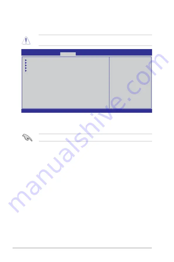
Be cautious when changing the settings of the Advanced menu items. Incorrect field values 

can cause the system to malfunction.

2.5 

Advanced menu

The Advanced menu items allow you to change the settings for the CPU and other system 

devices.

v02.61 (C)Copyright 1985-2009, American Megatrends, Inc.

BIOS SETUP UTILITY

 Main    Ai Tweaker   

 Advanced

    Power    Boot    Tools    Exit

Configure CPU.

←→

      Select  Screen 

↑↓

        S e l e c t  I t e m 

Enter Go to Sub Screen 

F1        General  Help 

F10      Save  and  Exit 

ESC   Exit

  CPU Configuration

  North Bridge Configuration

  Onboard Devices Configuration

  USB Configuration

  PCIPnP

Intel VT-d  


  [Disabled]

v02.61 (C)Copyright 1985-2009, American Megatrends, Inc.

CPU Ratio Setting [Auto]

Allows you to adjust the ratio between CPU Core Clock and BCLK Frequency. Use the <+> 

and <-> keys to adjust the value. The valid value ranges differently according to your CPU 

model.

C1E Support [Enabled]

[Enabled] 

Enables the C1E support function. This item should be enabled in order to  


enable the Enhanced Halt Sate.

[Disabled] 

Disables this function.

Hardware Prefetcher [Enabled]

[Enabled] 

Enables the Hardware Prefetcher function. This item should be enabled 


 in order to enable the L2 cache (MLC) Streamer Prefetcher for tuning 


performance of the specific application.

[Disabled] 

Disables this function.

Adjacent Cache Line Prefetcher [Enabled]

[Enabled] 

Enables the Adjacent Cache Line Prefetcher function. This item should be  


enabled in order to enable the L2 cache (MLC) Spatial Prefetcher for tuning 


performance of the specific application.

[Disabled] 

Disables this function.

Summary of Contents for P7P55 LX JOOYON SI

Page 1: ...Motherboard P7P55 LX ...

Page 2: ...CULAR PURPOSE IN NO EVENT SHALL ASUS ITS DIRECTORS OFFICERS EMPLOYEES OR AGENTS BE LIABLE FOR ANY INDIRECT SPECIAL INCIDENTAL OR CONSEQUENTIAL DAMAGES INCLUDING DAMAGES FOR LOSS OF PROFITS LOSS OF BUSINESS LOSS OF USE OR DATA INTERRUPTION OF BUSINESS AND THE LIKE EVEN IF ASUS HAS BEEN ADVISED OF THE POSSIBILITY OF SUCH DAMAGES ARISING FROM ANY DEFECT OR ERROR IN THIS MANUAL OR PRODUCT SPECIFICATIO...

Page 3: ... 3 Motherboard layout 1 7 1 5 4 Layout contents 1 7 1 6 Central Processing Unit CPU 1 8 1 6 1 Installing the CPU 1 8 1 6 2 Installing the CPU heatsink and fan 1 11 1 6 3 Uninstalling the CPU heatsink and fan 1 12 1 7 System memory 1 13 1 7 1 Overview 1 13 1 7 2 Memory configurations 1 14 1 7 3 Installing a DIMM 1 18 1 7 4 Removing a DIMM 1 18 1 8 Expansion slots 1 19 1 8 1 Installing an expansion ...

Page 4: ...ater 2 3 2 2 BIOS setup program 2 6 2 2 1 BIOS menu screen 2 7 2 2 2 Menu bar 2 7 2 2 3 Navigation keys 2 8 2 2 4 Menu items 2 8 2 2 5 Submenu items 2 8 2 2 6 Configuration fields 2 8 2 2 7 Pop up window 2 8 2 2 8 Scroll bar 2 8 2 2 9 General help 2 8 2 3 Main menu 2 9 2 3 1 System Time 2 9 2 3 2 System Date 2 9 2 3 3 SATA1 6 2 9 2 3 4 Storage Configuration 2 10 2 3 5 AHCI Configuration 2 11 2 3 6...

Page 5: ...ration 2 18 2 5 2 North Bridge Configuration 2 20 2 5 3 Onboard Devices Configuration 2 20 2 5 4 USB Configuration 2 20 2 5 5 PCIPnP 2 21 2 5 6 Intel VT d 2 21 2 6 Power menu 2 21 2 6 1 Suspend Mode 2 22 2 6 2 ACPI 2 0 Support 2 22 2 6 3 ACPI APIC Support 2 22 2 6 4 APM Configuration 2 22 2 6 5 Hardware Monitor 2 23 2 7 Boot menu 2 24 2 7 1 Boot Device Priority 2 24 2 7 2 Boot Settings Configurati...

Page 6: ...t from that to which the receiver is connected Consult the dealer or an experienced radio TV technician for help The use of shielded cables for connection of the monitor to the graphics card is required to assure compliance with FCC regulations Changes or modifications to this unit not expressly approved by the party responsible for compliance could void the user s authority to operate this equipm...

Page 7: ...t to the correct voltage in your area If you are not sure about the voltage of the electrical outlet you are using contact your local power company If the power supply is broken do not try to fix it by yourself Contact a qualified service technician or your retailer The optical S PDIF is an optional component may or may not be included in your motherboard and is defined as a CLASS 1 LASER PRODUCT ...

Page 8: ...ard and adding devices on it carefully read all the manuals that came with the package Before using the product ensure that all cables are correctly connected and the power cables are not damaged If you detect any damage contact your dealer immediately To avoid short circuits keep paper clips screws and staples away from connectors slots sockets and circuitry Avoid dust humidity and temperature ex...

Page 9: ...ct and software updates 1 ASUS websites The ASUS website provides updated information on ASUS hardware and software products Refer to the ASUS contact information 2 Optional documentation Your product package may include optional documentation such as warranty flyers that may have been added by your dealer These documents are not part of the standard package Typography Bold text Indicates a menu o...

Page 10: ...ing system may only recognize less than 3GB We recommend a maximum of 3GB system memory if you are using a Windows 32 bit operating system Expansion slots 1 x PCI Express 2 0 x16 slot single at x16 1 x PCI Express 2 0 x16 slot at x4 mode 2 5GT s 2 x PCI Express 2 0 x1 slots 2 5GT s 3 x PCI slots Multi GPU Support Supports ATI Quad GPU CrossFireX technology Storage Intel P55 Express Chipset 6 x SAT...

Page 11: ...Adjustable CPU voltage at 0 00625V increment vIMC Adjustable IMC voltage at 0 05V increment vDRAM Bus 11 step DRAM voltage control vPCH 2 step chipset voltage control vCPU PLL 4 step reference voltage control SFS Stepless Frequency Selection Internal Base Clock tuning from 80 MHz up to 500 MHz at 1MHz increment PCI Express frequency tuning from 100MHz up to 150MHz at 1MHz increment Overclocking Pr...

Page 12: ...anel connector 1 x MemOK button 1 x COM connector BIOS 16 Mb Flash ROM AMI BIOS PnP DMI 2 0 WfM 2 0 SM BIOS 2 5 ACPI 2 0a Multi language BIOS ASUS EZ Flash 2 ASUS CrashFree BIOS 3 Manageability WfM 2 0 DMI 2 0 WOL by PME WOR by PME PXE Accessories 1 x Ultra DMA 133 100 66 cable 2 x Serial ATA 3 0Gb s cables 1 x I O shield 1 x User Manual Support DVD Drivers ASUS Utilities ASUS Update Anti virus so...

Page 13: ... LGA1156 package which has memory and PCI Express controller integrated to support 2 channel 4 DIMMs DDR3 memory and 16 PCI Express 2 0 lanes providing great graphics performance Intel Lynnfield processor is one of the most powerful and energy efficient CPU in the world 1 1 Welcome Thank you for buying an ASUS P7P55 LX motherboard The motherboard delivers a host of new features and latest technolo...

Page 14: ...width of your system memory to boost system performance Serial ATA 3Gb s technology and RAID support This motherboard supports hard drives based on the Serial ATA SATA 3Gb s storage specifications delivering enhanced salability and doubling the bus bandwidth for high speed data saving and retrieval It also supports RAID 0 RAID 1 RAID 5 and RAID 10 configurations for Serial ATA hard drives S PDIF d...

Page 15: ...d key applications before entering the Windows OS ASUS Express Gate supports installation on SATA HDDs USB HDDs and flash drives with at least 1 2GB free disk space When installing it on USB HDDs or flash drives connect the drives to the motherboard USB port before turning on the computer The actual boot time depends on the system configuration ASUS Express Gate supports file uploading from SATA H...

Page 16: ... after turning on the system and any faulty cable connections are reported back up to 100 meters at 1 meter accuracy C P R CPU Parameter Recall The BIOS C P R feature automatically restores the CPU default settings when the system hangs due to overclocking failure C P R eliminates the need to open the system chassis and clear the RTC data Simply shut down and reboot the system and the BIOS automat...

Page 17: ...ace it on a grounded antistatic pad or in the bag that came with the component Before you install or remove any component ensure that the ATX power supply is switched off or the power cord is detached from the power supply Failure to do so may cause severe damage to the motherboard peripherals or components Onboard LED The motherboard comes with a standby power LED that lights up to indicate that ...

Page 18: ...l injury and damage motherboard components 1 5 1 Placement direction When installing the motherboard ensure that you place it into the chassis in the correct orientation The edge with external ports goes to the rear part of the chassis as indicated in the image below 1 5 2 Screw holes Place six screws into the holes indicated by circles to secure the motherboard to the chassis Do not overtighten t...

Page 19: ...n ATX12V 1 26 10 Clear RTC RAM 3 pin CLRTC 1 20 3 USB device wake up 3 pin USBPW1 8 3 pin USBPW9 14 1 21 11 System panel connector 20 8 pin PANEL 1 29 4 CPU power and chassis fan connectors 4 pin CPU_FAN 3 pin PWR_FAN 3 pin CHA_FAN 1 27 12 USB connectors 10 1 pin USB910 USB1112 USB1314 1 26 5 LGA1156 CPU socket 1 8 13 Digital audio connector 4 1 pin SPDIF_OUT 1 27 6 DDR3 DIMM slots 1 13 14 Optical...

Page 20: ... is shipment transit related Keep the cap after installing the motherboard ASUS will process Return Merchandise Authorization RMA requests only if the motherboard comes with the cap on the LGA1156 socket The product warranty does not cover damage to the socket contacts resulting from incorrect CPU installation removal or misplacement loss incorrect removal of the PnP cap 1 6 1 Installing the CPU T...

Page 21: ...cap The CPU fits in only one correct orientation DO NOT force the CPU into the socket to prevent bending the connectors on the socket and damaging the CPU Gold triangle mark Alignment keys CPU notches 5 Position the CPU over the socket ensuring that the gold triangle is on the bottom left corner of the socket and then fit the socket alignment keys into the CPU notches ...

Page 22: ...retention tab 6 Apply some Thermal Interface Material to the exposed area of the CPU that the heatsink will be in contact with ensuring that it is spread in an even thin layer Some heatsinks come with pre applied thermal paste If so skip this step The Thermal Interface Material is toxic and inedible DO NOT eat it If it gets into your eyes or touches your skin wash it off immediately and seek profe...

Page 23: ...sure that you have installed the motherboard to the chassis before you install the CPU fan and heatsink assembly The type of CPU heatsink and fan assembly may differ but the installation steps and functions should remain the same The illustration above is for reference only To install the CPU heatsink and fan 1 Place the heatsink on top of the installed CPU ensuring that the four fasteners match t...

Page 24: ...is connector 1 6 3 Uninstalling the CPU heatsink and fan To uninstall the CPU heatsink and fan 1 Disconnect the CPU fan cable from the connector on the motherboard 2 Rotate each fastener counterclockwise 3 Pull up two fasteners at a time in a diagonal sequence to disengage the heatsink and fan assembly from the motherboard A A B B A A B B CPU_FAN GND CPU FAN PWR CPU FAN IN CPU FAN PWM P7P55 LX P7P...

Page 25: ...nt installation on a DDR2 DIMM socket DDR3 modules are developed for better performance with less power consumption The figure illustrates the location of the DDR3 DIMM sockets Channel Sockets Channel A DIMM_A1 and DIMM_A2 Channel B DIMM_B1 and DIMM_B2 4 Carefully remove the heatsink and fan assembly from the motherboard 5 Rotate each fastener clockwise to ensure correct orientation when reinstall...

Page 26: ...r one DIMM per channel only According to Intel CPU spec DIMM voltage below 1 65V is recommended to protect the CPU According to Intel CPU spec CPUs with a core frequency of 2 66GHz support the maximum DIMM frequency of up to DDR3 1333 To use DIMMs of a higher frequency with a 2 66GHz CPU enable the DRAM O C Profile feature in BIOS Refer to section 2 4 Ai Overclock Tuner for details Always install ...

Page 27: ...4 Crucial BL25664TR1608 K16SF XMP 6144MB Kit of 3 DS N A Heat Sink Package 8 8 8 24 G SKILL F3 12800CL9D 2GBNQ 2048MB Kit of 2 SS N A Heat Sink Package 9 9 9 24 1 5V 1 6V G SKILL F3 12800CL8T 6GBHK 2048MB DS N A Heat Sink Package 8 8 8 21 1 6 1 65 G SkiLL F3 12800CL8T 6GBPI XMP 6144MB Kit of 3 DS N A Heat Sink Package 8 8 8 21 1 6 1 65V G SKILL F3 12800CL9T 6GBNQ 6144MB Kit of 3 DS N A Heat Sink P...

Page 28: ...BPI 1024MB DS G SKILL Heat Sink Package G SKILL F3 10600CL9D 2GBNQ 1024MB DS G SKILL Heat Sink Package G SkiLL F3 10666CL8D 4GBHK 4096MB Kit of 2 DS N A Heat Sink Package 8 8 8 21 1 5 1 6V G SKILL F3 10666CL7T 6GBPK 6144MB Kit of 3 DS N A Heat Sink Package 7 7 7 18 1 5 1 6V G SKILL F3 10666CL9T 6GBNQ 6144MB Kit of 3 DS N A Heat Sink Package 9 9 9 24 1 5V 1 6V GEIL DDR3 1333 CL9 9 9 24 1024MB SS N ...

Page 29: ...n C Supports four modules inserted into both the blue and black slots as two pairs of Dual channel memory configuration Vendor Part No Size SS DS Chip Brand Chip NO CL Voltage DIMM socket support optinal A B C SAMSUNG M378B5673DZ1 CH9 2048MB DS Samsung K4B1G0846D HCH9 SAMSUNG M378B5673EH1 CH9 2048MB DS Samsung SEC 913 HCH9 K4B1G0846E SAMSUNG M391B5673DZ1 CH9 2048MB DS Samsung K4B1G0846D HCH9 ECC S...

Page 30: ...nstall a DIMM 1 Unlock a DIMM socket by pressing the retaining clip outward 2 Align a DIMM on the socket such that the notch on the DIMM matches the break on the socket Support the DIMM lightly with your fingers when pressing the retaining clip The DIMM might get damaged when it flips out with extra force Ensure to unplug the power supply before adding or removing DIMMs or other system components ...

Page 31: ...cover 1 8 2 Configuring an expansion card After installing the expansion card configure it by adjusting the software settings 1 Turn on the system and change the necessary BIOS settings if any See Chapter 2 for information on BIOS setup 2 Assign an IRQ to the card 3 Install the software drivers for the expansion card When using PCI cards on shared slots ensure that the drivers support Share IRQ or...

Page 32: ...down and reboot the system then the BIOS automatically resets parameter settings to default values Due to the chipset limitation AC power off is required before you use the C P R function You must turn off and on the power supply or unplug and plug the power cord before rebooting the system To erase the RTC RAM 1 Turn OFF the computer and unplug the power cord 2 Move the jumper cap from pins 1 2 d...

Page 33: ...p the computer from S1 sleep mode CPU stopped DRAM refreshed system running in low power mode using the connected USB devices Set to 5VSB to wake up from S3 and S4 sleep modes no power to CPU DRAM in slow refresh power supply in reduced power mode The USB device wake up feature requires a power supply that can provide 500mA on the 5VSB lead for each USB port otherwise the system would not power up...

Page 34: ...Ms during the tuning process the system continues memory tuning after turning on the computer To stop memory tuning turn off the computer and unplug the power cord for about 5 10 seconds If your system fail to boot due to BIOS overclocking press the MemOK switch to boot and load BIOS default settings A messgae will appear during POST reminding you that the BIOS has been restored to its default set...

Page 35: ...port connects the center subwoofer speakers 4 Rear Speaker Out port black This port connects the rear speakers in a 4 channel 6 channel or 8 channel audio configuration 5 Line In port light blue This port connects the tape CD DVD player or other audio sources 6 Line Out port lime This port connects a headphone or a speaker In 4 channel 6 channel and 8 channel configurations the function of this po...

Page 36: ...enter Subwoofer Black Rear Speaker Out Rear Speaker Out Rear Speaker Out Gray Side Speaker Out 1 11 2 Internal connectors 1 Front panel audio connector 10 1 pin AAFP This connector is for a chassis mounted front panel audio I O module that supports either HD Audio or legacy AC 97 audio standard Connect one end of the front panel audio I O module cable to this connector We recommend that you connec...

Page 37: ... gray Slave Slave Pin 20 on the IDE connector is removed to match the covered hole on the Ultra DMA cable connector This prevents incorrect insertion when you connect the IDE cable Use the 80 conductor IDE cable for Ultra DMA 133 100 66 IDE devices If any device jumper is set as Cable Select ensure that all other device jumpers have the same setting 3 Optical drive audio connector 4 pin CD These c...

Page 38: ...the connectors completely fit 5 USB connectors 10 1 pin USB910 USB1112 USB1314 These connectors are for USB 2 0 ports Connect the USB module cable to any of these connectors then install the module to a slot opening at the back of the system chassis These USB connectors comply with USB 2 0 specification that supports up to 480 Mbps connection speed Never connect a 1394 cable to the USB connectors ...

Page 39: ... chassis fan connectors 4 pin CPU_FAN 3 pin PWR_FAN 3 pin CHA_FAN Connect the fan cables to the fan connectors on the motherboard ensuring that the black wire of each cable matches the ground pin of the connector Only the 4 pin CPU fan supports the ASUS Q FAN feature The CPU_FAN connector supports a CPU fan of maximum 2A 24 W fan power Only the CPU_FAN and CHA_FAN connectors support the FAN Xpert ...

Page 40: ... 2 or later version before using Serial ATA hard disk drives The Serial ATA RAID feature RAID 0 1 5 and 10 is available only if you are using Windows XP SP2 or later version When using hot plug and NCQ set the Configure SATA as item in the BIOS to AHCI See section 2 3 4 Storage Configuration for details 9 Serial port connector 10 1 pin COM1 This connector is for a serial COM port Connect the seria...

Page 41: ...hts up or flashes when data is read from or written to the HDD System warning speaker 4 pin SPEAKER This 4 pin connector is for the chassis mounted system warning speaker The speaker allows you to hear system beeps and warnings ATX power button soft off button 2 pin PWRSW This connector is for the system power button Pressing the power button turns the system on or puts the system in sleep or soft...

Page 42: ...ty 1 12 2 Support DVD information The Support DVD that comes with the motherboard package contains the drivers software applications and utilities that you can install to avail all motherboard features If Autorun is NOT enabled in your computer browse the contents of the Support DVD to locate the file ASSETUP EXE from the BIN folder Double click the ASSETUP EXE to run the DVD The following screen ...

Page 43: ...pdown list select any of the updating process Updating from the Internet a Select Update BIOS from the Internet then click Next b Select the ASUS FTP site nearest you to avoid network traffic or click Auto Select then click Next c From the FTP site select the BIOS version that you wish to download then click Next 2 1 1 ASUS Update utility The ASUS Update is a utility that allows you to manage save...

Page 44: ...he BIOS update process and automatically reboots the system when done The ASUS Update utility is capable of updating itself through the Internet Always update the utility to avail all its features Updating from a BIOS file a Select Update BIOS from a file then click Next b Locate the BIOS file from the Open window then click Open 3 Follow the onscreen instructions to complete the updating process ...

Page 45: ...pported 3 The utility automatically checks the devices for the BIOS file When found the utility reads the BIOS file and starts flashing the corrupted BIOS file 4 Turn off the system after the utility completes the updating process and turn on again DO NOT shut down or reset the system while updating the BIOS Doing so can cause system boot failure Ensure to load the BIOS default settings to ensure ...

Page 46: ...by pressing the item number 4 At the FreeDOS prompt type d and press Enter to switch the disk from Drive C optical drive to Drive D USB flash drive Please select boot device and to move selection ENTER to select boot device ESC to boot using defaults SATA XXXXXXXXXXXXXXXX CDROM XXXXXXXXXXXXXXX USB XXXXXXXXXXXXXXXXX Network XXXXXXXXXXXXX 2 The BIOS Updater backup screen appears indicating the BIOS ...

Page 47: ...STek BIOS Updater for DOS V1 00b 09 06 22 Current ROM Update ROM A Note Enter Select or Load Tab Switch V Drive Info Up Down Home End Move B Backup Esc Exit P7P55 LX ROM 2097152 2009 09 03 17 30 48 FLASH TYPE MXIC 25L1605A PATH A BOARD P7P55 LX VER 0304 DATE 09 03 2009 BOARD Unknown VER Unknown DATE Unknown D bupdater pc g 2 The BIOS Updater screen appears as below 3 Press Tab to switch between sc...

Page 48: ...t the system while updating the BIOS to prevent system boot failure For BIOS Updater version 1 04 or later the utility automatically exits to the DOS prompt after updating BIOS Ensure to load the BIOS default settings to ensure system compatibility and stability Select the Load Setup Defaults item under the Exit menu Refer to section 2 9 Exit menu for details Ensure to connect all SATA hard disk d...

Page 49: ... menu bar press the right or left arrow key on the keyboard until the desired item is highlighted 2 2 1 BIOS menu screen Select Screen Select Item Change Field Tab Select Field F1 General Help F10 Save and Exit ESC Exit v02 61 C Copyright 1985 2009 American Megatrends Inc Use ENTER TAB or SHIFT TAB to select a field Use or to configure system Time Navigation keys General help Menu bar Submenu item...

Page 50: ...ble A configurable field is enclosed in brackets and is highlighted when selected To change the value of a field select it then press Enter to display a list of options Refer to 2 2 7 Pop up window 2 2 7 Pop up window Select a menu item then press Enter to display a pop up window with the configuration options for that item 2 2 8 Scroll bar A scroll bar appears on the right side of a menu screen w...

Page 51: ...LBA Mode Block Mode PIO Mode Async DMA Ultra DMA and SMART monitoring These values are not user configurable These items show Not Detected if no SATA device is installed in the system Type Auto Selects the type of SATA drive Setting to Auto allows automatic selection of the appropriate SATA device type Select CDROM if you are specifically configuring a CD ROM drive Select ARMD ATAPI Removable Medi...

Page 52: ...n Enhanced Configuration options Disabled Compatible Enhanced Configure SATA as IDE Sets the configuration for the Serial ATA connectors supported by the Southbridge chip Configuration options IDE RAID AHCI If you want to use the Serial ATA hard disk drives as Parallel ATA physical storage devices keep the default setting IDE If you want the Serial ATA hard disk drives to use the Advanced Host Con...

Page 53: ...of device connected to the system Configuration options Auto Not Installed SMART Monitoring Enabled Allows you to set the Self Monitoring Analysis and Reporting Technology Configration options Disabled Enabled 2 3 6 System Information This menu gives you an overview of the general system specifications The BIOS automatically detects the items in this menu BIOS Information Displays the auto detecte...

Page 54: ...enquency Auto DRAM Timing Control CPU Clock Skew Auto v02 61 C Copyright 1985 2009 American Megatrends Inc Please key in numbers directly VCore Over Voltage Offset Offset Voltage Auto IMC Voltage Auto CPU PLL Voltage Auto PCH Voltage Auto DRAM Voltage 1 6V Load Line Calibration The configuration options for this chapter vary depending on the CPU and DIMM model you installed on the motherboard 2 4 ...

Page 55: ...Enabled When set to Disabled the CPU runs at its default speed When set to Enabled the CPU speed is controlled by the operating system Configuration options Disabled Enabled 2 4 4 Intel R TurboMode Tech Enabled This item appears only if you set the Ratio CMOS Setting item to Auto Turbo mode allows processor cores to run faster than marked frequency in specific condition Configuration options Disab...

Page 56: ...DRAM frequency may cause the system to become unstable If this happens revert to the default setting 2 4 7 QPI Frequency Auto Allows you to set the QPI operating frequency Configuration options Auto 4270MHz 4800MHz 2 4 8 DRAM Timing Control Auto The items in this menu allow you to set the DRAM timing control features The configuration options for some of the following items vary depending on the D...

Page 57: ...e Auto Configuration options Auto 1N 2N 3N DRAM Round Trip Latency on CHA Auto Auto Advance 15 Clock Advance 1 Clock Normal Delay 1 Clock Delay 15 Clock DRAM Round Trip Latency on CHB Auto Auto Advance 15 Clock Advance 1 Clock Normal Delay 1 Clock Delay 15 Clock 3rd Information 8 8 25 17 17 17 9 9 6 9 9 6 The values vary depending on your settings of the following sub items DRAM WRITE to READ Dela...

Page 58: ...tore the default setting type auto using the keyboard and press the Enter key 2 4 10 VCore Over Voltage Offset Allows you to set the CPU Vcore over voltage Different sub items appear according to the VCore Over Voltage item setting Configuration options Offset Manual Offset Voltage Auto This item appears only when you set the Vcore Over Voltage item to Offset and allows you to set the Offset volta...

Page 59: ... values range from 1 05V to 1 15V with a 0 10V interval The system may need better cooling system to work stably under high voltage settings 2 4 14 DRAM Voltage Auto Allows you to set the DRAM voltage The values range from 1 2V to 2 2V with a 0 05V or 0 1V interval From 1 5V to 1 7V the interval is 0 05V According to Intel CPU spec DIMMs with voltage requirement over 1 65V may damage the CPU perma...

Page 60: ... Configuration PCIPnP Intel VT d Disabled v02 61 C Copyright 1985 2009 American Megatrends Inc CPU Ratio Setting Auto Allows you to adjust the ratio between CPU Core Clock and BCLK Frequency Use the and keys to adjust the value The valid value ranges differently according to your CPU model C1E Support Enabled Enabled Enables the C1E support function This item should be enabled in order to enable t...

Page 61: ...PU core is enabled Active Processor Cores All All Activate all CPU cores in the processor package 1 Activate only 1 CPU core in the processor package 2 Activate 2 CPU cores in the processor package A20M Disabled Enabled Legacy OSes and APs may need this function enabled Disabled Disables this function Intel R SpeedStep TM Tech Enabled Enabled The CPU speed is controlled by the operating system Dis...

Page 62: ...LAN Controller Configuration options Enabled Disabled Onboard LAN Boot ROM Disabled This item appears only when you enable the previous item s Disables or disables the onboard LAN Boot ROM Configuration options Enabled Disabled Onboard IDE Controller Enabled Enables or disables the onboard IDE Controller Configuration options Enabled Disabled Serial Port1 Address 3F8 IRQ4 Allows you to select the ...

Page 63: ... No BIOS configures all the devices in the system When set to Yes and if you install a Plug and Play operating system the operating system configures the Plug and Play devices not required for boot Configuration options No Yes 2 5 6 Intel VT d Disabled Enables or disables the Intel Virtualization Technology for Directed I O Configuration options Enabled Disabled 2 6 Power menu The Power menu items...

Page 64: ...ist 2 6 4 APM Configuration Restore On AC Power Loss Power Off Power Off The system goes into off state after an AC power loss Power On The system goes into on state after an AC power loss Last State The system goes into either off or on state whatever the system state was before the AC power loss Power On By RTC Alarm Disabled Disabled Disables RTC to generate a wake event Enabled When set to Ena...

Page 65: ...are Monitor CPU MB Temperature xxxºC xxxºF The onboard hardware monitor automatically detects and displays the CPU and motherboard temperatures Select Ignored if you do not wish to display the detected temperatures CPU Chassis Power Fan Speed xxxxRPM or Ignored N A The onboard hardware monitor automatically detects and displays the CPU chassis and power fan speed in rotations per minute RPM If the...

Page 66: ...isplay the submenu v02 61 C Copyright 1985 2009 American Megatrends Inc BIOS SETUP UTILITY Main Ai Tweaker Advanced Power Boot Tools Exit Specifies the Boot Device Priority sequence A virtual floppy disk drive Floppy Drive B may appear when you set the CD ROM drive as the first boot device Select Screen Select Item Enter Go to Sub Screen F1 General Help F10 Save and Exit ESC Exit Boot Settings Boo...

Page 67: ... the message Press DEL to run Setup during POST Configuration options Disabled Enabled 2 7 3 Security The Security menu items allow you to change the system security settings Select an item then press Enter to display the configuration options Change Supervisor Password Select this item to set or change the supervisor password The Supervisor Password item on top of the screen shows the default Not...

Page 68: ...nge User Password item and press Enter 2 In the password box key in a password containing up to six letters or numbers or both then press Enter 3 Confirm the password when prompted The message Password Installed appears after you set your password successfully To change the user password follow the same steps as in setting a user password Clear User Password Select this item to clear the user pass...

Page 69: ...king of the Realtek LAN cable during the Power On Self Test POST Configuration options Disabled Enabled 2 8 3 Express Gate Auto Allows you to enable or disable the ASUS Express Gate feature The ASUS Express Gate feature is a unique instant on environment that provides quick access to the Internet browser and Skype Configuration options Disabled Enabled Auto Enter OS Timer 10 Seconds Sets countdown...

Page 70: ...u select this option a confirmation window appears Select Ok to save changes and exit Exit Discard Changes Select this option only if you do not want to save the changes that you made to the Setup program If you made changes to fields other than System Date System Time and Password the BIOS asks for a confirmation before exiting Discard Changes This option allows you to discard the selections you ...

Reviews: