background image

1-16

Chapter 1: Product introduction

1.7 

System memory

1.7.1 

Overview

The motherboard comes with two Double Data Rate 2 (DDR2) Dual Inline Memory 

Modules (DIMM) sockets.
A DDR2 module has the same physical dimensions as a DDR DIMM but has a 

240-pin footprint compared to the 184-pin DDR DIMM. DDR2 DIMMs are notched 

differently to prevent installation on a DDR DIMM socket.

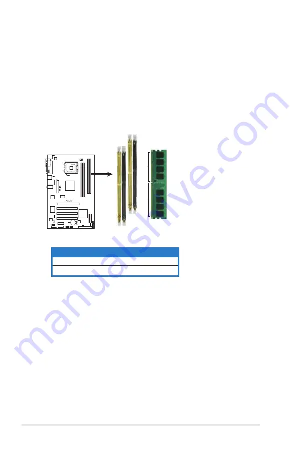
The figure illustrates the location of the DDR2 DIMM sockets:


Channel 

Sockets


Channel A 

DIMM_A1 and DIMM_A2


Channel B 

DIMM_B1 and DIMM_B2

P5KPL

P5KPL 

240-pin DDR2 DIMM Socket

s

128 Pins

112 Pins

DIMM_A2

DIMM_B1

DIMM_B2

DIMM_A1

Summary of Contents for P5KPL IPC/SI

Page 1: ...Motherboard P5KPL ...

Page 2: ... MERCHANTABILITY OR FITNESS FOR A PARTICULAR PURPOSE IN NO EVENT SHALL ASUS ITS DIRECTORS OFFICERS EMPLOYEES OR AGENTS BE LIABLE FOR ANY INDIRECT SPECIAL INCIDENTAL OR CONSEQUENTIAL DAMAGES INCLUDING DAMAGES FOR LOSS OF PROFITS LOSS OF BUSINESS LOSS OF USE OR DATA INTERRUPTION OF BUSINESS AND THE LIKE EVEN IF ASUS HAS BEEN ADVISED OF THE POSSIBILITY OF SUCH DAMAGES ARISING FROM ANY DEFECT OR ERROR...

Page 3: ... 3 Motherboard layout 1 7 1 5 4 Layout contents 1 8 1 6 Central Processing Unit CPU 1 9 1 6 1 Installing the CPU 1 10 1 6 2 Installing the CPU heatsink and fan 1 12 1 6 3 Uninstalling the CPU heatsink and fan 1 14 1 7 System memory 1 16 1 7 1 Overview 1 16 1 7 2 Memory configurations 1 17 1 7 3 Installing a DIMM 1 21 1 7 4 Removing a DIMM 1 21 1 8 Expansion slots 1 22 1 8 1 Installing an expansion...

Page 4: ... Menu bar 2 13 2 2 3 Navigation keys 2 13 2 2 4 Menu items 2 14 2 2 5 Sub menu items 2 14 2 2 6 Configuration fields 2 14 2 2 7 Pop up window 2 14 2 2 8 Scroll bar 2 14 2 2 9 General help 2 14 2 3 Main menu 2 15 2 3 1 System Time 2 15 2 3 2 System Date 2 15 2 3 3 Legacy Diskette A 2 15 2 3 4 Primary Third and Fourth IDE Master Slave 2 16 2 3 5 IDE Configuration 2 17 2 3 6 System Information 2 18 2...

Page 5: ...ty 2 32 2 7 Tools menu 2 34 ASUS EZ Flash 2 2 34 2 8 Exit menu 2 35 Chapter 3 Software support 3 1 Installing an operating system 3 2 3 2 Support CD information 3 2 3 2 1 Running the support CD 3 2 3 2 2 Drivers menu 3 3 3 2 3 Utilities menu 3 4 3 2 4 ASUS Contact information 3 5 Appendix CPU features A 1 Intel EM64T A 2 A 2 Enhanced Intel SpeedStep Technology EIST A 2 A 2 1 System requirements A ...

Page 6: ...ause harmful interference to radio or television reception which can be determined by turning the equipment off and on the user is encouraged to try to correct the interference by one or more of the following measures Reorient or relocate the receiving antenna Increase the separation between the equipment and receiver Connect the equipment to an outlet on a circuit different from that to which the...

Page 7: ... the power supply is broken do not try to fix it by yourself Contact a qualified service technician or your retailer Operation safety Before installing the motherboard and adding devices on it carefully read all the manuals that came with the package Before using the product make sure all cables are correctly connected and the power cables are not damaged If you detect any damage contact your deal...

Page 8: ...gh the BIOS Setup menus Detailed descriptions of the BIOS parameters are also provided Chapter 3 Software support This chapter describes the contents of the support CD that comes with the motherboard package Appendix CPU features This Appendix describes the CPU features that the motherboard supports Where to find more information Refer to the following sources for additional information and for pr...

Page 9: ...y2 Key3 If you must press two or more keys simultaneously the key names are linked with a plus sign Example Ctrl Alt D Command Means that you must type the command exactly as shown then supply the required item or value enclosed in brackets Example At the DOS prompt type the command line afudos i filename afudos iP5KPL ROM DANGER WARNING Information to prevent injury to yourself when trying to com...

Page 10: ...CI Express x16 slot 1 x PCI Express x1 slot 3 x PCI slots Storage Southbridge Intel ICH7 supports 1 x UltraDMA 100 66 hard disk drive 4 x SATA 150 300 ports LAN PCIe Gigabit LAN controller Audio Realtek ALC 662 6 channel High Definition Audio CODEC Supports Jack detect S PDIF out interface Anti Pop Funtion Compatible with Vista Premium OS ASUS Overclocking Features SFS Stepless Frequency Selection...

Page 11: ...X 12 V power connector System panel connector USB Max 8 x USB2 0 ports 4 ports at mid board 4 ports at back panel BIOS features 8 Mb Flash ROM AMI BIOS Special H W write protection PnP DMI v2 0 WfM2 0 SM BIOS v2 5 ACPI Manageability WOL by PXE WOR by PXE WOR by Ring Supported OS Windows Vista XP 2000 Support CD contents Drivers ASUS PC Probe II ASUS LiveUpdate utility Accessories 2 x Serial ATA ca...

Page 12: ...xii ...

Page 13: ...1 Product introduction This chapter describes the motherboard features and the new technologies it supports ...

Page 14: ...ld Application CD ASUS motherboard support CD Documentation User guide 1 3 Special features 1 3 1 Product highlights Green ASUS This motherboard and its packaging comply with the European Union s Restriction on the use of Hazardous Substances RoHS This is in line with the ASUS vision of creating environment friendly and recyclable products packaging to safeguard consumers health while minimizing t...

Page 15: ... install DIMMs with different memory size and enjoy dual channel feature at the same time See page 1 16 for details Serial ATA 3 Gb s technology This motherboard supports the next generation hard drives based on the Serial ATA SATA 3 Gb s storage specification delivering enhanced scalability and doubling the bus bandwidth for high speed data retrieval and saves Easily backup photos videos and othe...

Page 16: ...BIOS without entering the OS Update your BIOS easily without preparing a bootable diskette or using an OS based flash utility See page 2 4 for details ASUS CrashFree BIOS 3 The ASUS CrashFree BIOS 3 allows users to restore corrupted BIOS data from a USB flash disk containing the BIOS file See page 2 7 for details 1 3 3 ASUS Overclocking features C P R CPU Parameter Recall The C P R feature of the ...

Page 17: ... it on a grounded antistatic pad or in the bag that came with the component Before you install or remove any component ensure that the ATX power supply is switched off or the power cord is detached from the power supply Failure to do so may cause severe damage to the motherboard peripherals and or components Onboard LED The motherboard comes with a standby power LED that lights up to indicate that...

Page 18: ...erboard make sure that you place it into the chassis in the correct orientation The edge with external ports goes to the rear part of the chassis as indicated in the image below 1 5 2 Screw holes Place six 6 screws into the holes indicated by circles to secure the motherboard to the chassis Place this side towards the rear of the chassis Make sure to unplug the power cord before installing or remo...

Page 19: ...DIMMA2 64 bit 240 pin module CD 19 3cm 7 6in CPU_FAN SATA4 SATA2 SATA3 SATA1 Intel G31 Intel ICH7 A1 PRI_IDE CHASSIS CLRTC FLOPPY USB56 USB78 PCIEX16 PCI1 PCI2 PCI3 PCIEX1 CR2032 3V Lithium Cell CMOS Power 8Mb BIOS USBPW5 8 Super I O SPDIF_OUT AAFP ALC662 USBPW1 4 ATX12V KBPWR EATXPWR Attansic L1 PANEL SB_PWR ICS 9LPRS552AGLF CHA_FAN PWR_FAN Refer to section 1 10 Connectors for more information ab...

Page 20: ... 0 ports 3 and 4 1 28 9 Coaxial S PDIF Out port 1 28 10 Serial port 1 28 11 PS 2 keyboard port purple 1 28 Internal connectors Page 1 Floppy disk drive connector 34 1 pin FLOPPY 1 29 2 Digital Audio connector 4 1 pin SPDIF_OUT 1 29 3 IDE connector 40 1 pin PRI_IDE 1 30 4 ICH7 Serial ATA connectors 7 pin SATA1 SATA2 SATA3 SATA4 1 31 5 USB connectors 10 1 pin USB56 USB78 1 32 6 Optical drive audio c...

Page 21: ...ket contacts motherboard components ASUS will shoulder the cost of repair only if the damage is shipment transit related Keep the cap after installing the motherboard ASUS will process Return Merchandise Authorization RMA requests only if the motherboard comes with the cap on the LGA775 socket The product warranty does not cover damage to the socket contacts resulting from incorrect CPU installati...

Page 22: ...ntion tab Retention tab Load lever This side of the socket box should face you PnP cap A B To prevent damage to the socket pins do not remove the PnP cap unless you are installing a CPU 1 6 1 Installing the CPU To install a CPU 1 Locate the CPU socket on the motherboard Before installing the CPU make sure that the cam box is facing towards you and the load lever is on your left P5KPL P5KPL CPU Soc...

Page 23: ...nnect the chassis fan cable to the chassis fan connector to ensure system stability A B The CPU fits in only one correct orientation DO NOT force the CPU into the socket to prevent bending the connectors on the socket and damaging the CPU The motherboard supports Intel LGA775 processors with Hyper Threading Technology Refer to the Appendix for more information on these CPU features 4 Lift the load...

Page 24: ...e only Intel certified multi directional heatsink and fan Your Intel LGA775 heatsink and fan assembly comes in a push pin design and requires no tool to install If you purchased a separate CPU heatsink and fan assembly make sure that you have properly applied Thermal Interface Material to the CPU heatsink or CPU before you install the heatsink and fan assembly Make sure that you have installed the...

Page 25: ... two fasteners at a time in a diagonal sequence to secure the heatsink and fan assembly in place B A A A B B Do not forget to connect the CPU fan connector Hardware monitoring errors can occur if you fail to plug this connector A B P5KPL P5KPL CPU Fan Connector GND CPU FAN PWR CPU FAN IN CPU FAN PWM CPU_FAN ...

Page 26: ...n 1 Disconnect the CPU fan cable from the connector on the motherboard 2 Rotate each fastener counterclockwise 3 Pull up two fasteners at a time in a diagonal sequence to disengage the heatsink and fan assembly from the motherboard B B A A A A B B 4 Carefully remove the heatsink and fan assembly from the motherboard ...

Page 27: ...on when reinstalling Narrow end of the groove Refer to the documentation in the boxed or stand alone CPU fan package for detailed information on CPU fan installation The narrow end of the groove should point outward after resetting The photo shows the groove shaded for emphasis ...

Page 28: ...sical dimensions as a DDR DIMM but has a 240 pin footprint compared to the 184 pin DDR DIMM DDR2 DIMMs are notched differently to prevent installation on a DDR DIMM socket The figure illustrates the location of the DDR2 DIMM sockets Channel Sockets Channel A DIMM_A1 and DIMM_A2 Channel B DIMM_B1 and DIMM_B2 P5KPL P5KPL 240 pin DDR2 DIMM Sockets 128 Pins 112 Pins DIMM_A2 DIMM_B1 DIMM_B2 DIMM_A1 ...

Page 29: ...sizes in Channel A and Channel B The system maps the total size of the lower sized channel for the dual channel configuration Any excess memory from the higher sized channel is then mapped for single channel operation For single channel configuration install either two single sided memory modules or one double sided memory module When installing four DDR2 DIMM modules install the single sided memo...

Page 30: ...P Y5 512MB HY HYMP564U64AP8 Y4 AA N A Hynix SS HY5PS12821AFP Y4 512MB HY HYMP564U64AP8 Y5 AA N A Hynix SS HY5PS12821AFP Y5 1G HY HYMP512U64AP8 Y5 AB N A Hynix DS HY5PS12821AFP Y5 1G HY HYMP512U64CP8 Y5 AB 5 Hynix DS HY5PS12521CFP Y5 512MB Kingmax KLCC28F A8KB5 N A Kingmax SS KKEA88B4LAUG 29DX 1G Kingmax KLCD48F A8KB5 N A Kingmax DS KKEA88B4LAUG 29DX 512MB Apacer AU512E667C5KBGC 5 Apacer SS AM4B570...

Page 31: ... SS AD29608A8A 25EG80720 512MB MDT MDT 512MB 4 MDT SS 18D51280D 30648 1G MDT MDT 1024MB 4 MDT DS 18D51280D 30646E 512MB Twinmos 8D A3JK5MPETP 5 PSC SS A3R12E3GEF633ACAOY 1G Twinmos 8D B3KK5MPFTP 5 PSC DS A3R12E3GEF633ACAOY 512MB AENEON AET660UD00 30DA98Z N A AENEON SS AET93F30DA 0552 512MB AENEON AET660UD00 30DB97X 5 AENEON SS AET93R300B 0634 1G AENEON AET760UD00 30DA98Z N A AENEON DS AET93F30DA8E...

Page 32: ...endor Model CL Brand Side s Component A B C DIMM support 1G VDATA M2GVD6G3I4170I1E53 N A VDATA DS VD29608A8A 25EG30647 512MB PSC AL6E8E63B 8E1K 5 PSC SS A3R12E3HEF641B9A05 1G PSC AL7E8E63B 8E1K 5 PSC DS A3R12E3HEF641B9A05 512MB AENEON AET660UD00 25DB98X N A AENEON SS AET93F25DB 0621 1G AENEON AET760UD00 25DB97X 5 AENEON DS AET93R25DB 0640 512MB SIS SLY264M8 JGE 3 N A SIS SS DDRII6408 8E 7212 1G SI...

Page 33: ...M 2 Remove the DIMM from the socket A DDR2 DIMM is keyed with a notch so that it fits in only one direction Do not force a DIMM into a socket to avoid damaging the DIMM The DDR2 DIMM sockets do not support DDR DIMMs Do not install DDR DIMMs to the DDR2 DIMM sockets Unlocked retaining clip DDR2 DIMM notch Unplug the power supply before adding or removing DIMMs or other system components Failure to ...

Page 34: ...Secure the card to the chassis with the screw you removed earlier 6 Replace the system cover 1 8 2 Configuring an expansion card After installing the expansion card configure it by adjusting the software settings 1 Turn on the system and change the necessary BIOS settings if any See Chapter 2 for information on BIOS setup 2 Assign an IRQ to the card Refer to the tables on the next page 3 Install t...

Page 35: ...oft ACPI Compliant Sytem 10 5 IRQ holder for PCI steering 11 6 IRQ holder for PCI steering 12 7 PS 2 Compatible Mouse Port 13 8 Numeric Data Processor 14 9 Primary IDE Channel These IRQs are usually available for PCI devices IRQ assignments for this motherboard A B C D E F G H PCI1 shared PCI2 shared PCI3 shared PCIEX16_1 shared PCIEX1_1 shared Onboard USB controller 1 shared Onboard USB controlle...

Page 36: ...PCI Express x1 slot This motherboard supports PCI Express x1 network cards SCSI cards and other cards that comply with the PCI Express specifications The following figure shows a network card installed on the PCI Express x1 slot 1 8 6 PCI Express x16 slot This motherboard supports PCI Express x16 graphic cards that comply with the PCI Express specifications The figure shows a graphics card install...

Page 37: ...ll the battery 5 Plug the power cord and turn ON the computer 6 Hold down the Del key during the boot process and enter BIOS setup to re enter data You do not need to clear the RTC when the system hangs due to overclocking For system failure due to overclocking use the C P R CPU Parameter Recall feature Shut down and reboot the system so the BIOS can automatically reset parameter settings to defau...

Page 38: ...otherwise the system would not power up The total current consumed must NOT exceed the power supply capability 5VSB whether under normal condition or in sleep mode P5KPL P5KPL USB Device Wake Up 3 2 2 1 USBPW5 8 Default 5V 5VSB 3 2 2 1 USBPW1 4 Default 5V 5VSB 3 Keyboard power 3 pin KBPWR This jumper allows you to enable or disable the keyboard wake up feature Set this jumper to pins 2 3 5VSB to w...

Page 39: ...ort LED indications Activity Link Speed LED Status Description Status Description OFF No link OFF 10 Mbps connection YELLOW Linked ORANGE 100 Mbps connection BLINKING Data activity GREEN 1 Gbps connection LAN port LED indications SPEED LED ACT LINK LED LAN port 4 Line In port light blue This port connects the tape CD DVD player or other audio sources 5 Line Out port lime This port connects a headp...

Page 40: ...rnal audio output device via an optical S PDIF cable 10 Serial port This 9 pin COM1 port is for pointing devices or other serial devices 11 PS 2 keyboard port purple This port is for a PS 2 keyboard Audio 2 4 or 6 channel configuration Light Blue Line In Surround Out Surround Out Lime green Line Out Front Speaker Out Front Speaker Out Pink Mic In Mic Center Bass Port Headset 4 speaker 6 speaker 2 ...

Page 41: ...d to prevent incorrect cable connection when using a FDD cable with a covered Pin 5 P5KPL P5KPL Floppy Disk Drive Connector PIN1 NOTE Orient the red markings on the floppy ribbon cable to PIN 1 FLOPPY 2 Digital Audio connector 4 1 pin SPDIF_OUT This connector is for the S PDIF audio module to allow digital sound output Connect one end of the S PDIF audio cable to this connector and the other end t...

Page 42: ... to match the covered hole on the Ultra DMA cable connector This prevents incorrect insertion when you connect the IDE cable Use the 80 conductor IDE cable for Ultra DMA 100 66 33 IDE devices If any device jumper is set as Cable Select make sure all other device jumpers have the same setting Drive jumper setting Mode of device s Cable connector Single device Cable Select or Master Black Two device...

Page 43: ...RXN2 RSATA_RXP2 GND SATA2 GND RSATA_TXP4 RSATA_TXN4 GND RSATA_RXN4 RSATA_RXP4 GND SATA4 GND RSATA_TXP1 RSATA_TXN1 GND RSATA_RXN1 RSATA_RXP1 GND SATA1 GND RSATA_TXP3 RSATA_TXN3 GND RSATA_RXN3 RSATA_RXP3 GND SATA3 Connect the right angle side of SATA signal cable to SATA device Or you may connect the right angle side of SATA cable to the onboard SATA port to avoid mechanical conflict with huge graph...

Page 44: ...nectors are for USB 2 0 ports Connect the USB module cable to any of these connectors then install the module to a slot opening at the back of the system chassis These USB connectors comply with USB 2 0 specification that supports up to 480 Mbps connection speed P5KPL P5KPL USB 2 0 Connectors USB78 USB 5V USB_P8 USB_P8 GND NC USB 5V USB_P7 USB_P7 GND 1 USB56 USB 5V USB_P6 USB_P6 GND NC USB 5V USB_...

Page 45: ...re that the black wire of each cable matches the ground pin of the connector Do not forget to connect the fan cables to the fan connectors Insufficient air flow inside the system may damage the motherboard components These are not jumpers Do not place jumper caps on the fan connectors Only the CPU FAN connector supports the ASUS Advanced Q Fan feature P5KPL P5KPL Fan Connectors GND CPU FAN PWR CPU...

Page 46: ...t to HD Audio If you want to connect a High Definition front panel audio module to this connector set the Front Panel Support Type item in the BIOS to HD Audio See section 2 4 4 Chipset for details 8 Chassis intrusion connector 4 1 pin CHASSIS This connector is for a chassis mounted intrusion detection sensor or switch Connect one end of the chassis intrusion sensor or switch cable to this connect...

Page 47: ... power is inadequate The ATX 12 V Specification 2 0 compliant 400W PSU has been tested to support the motherboard power requirements 10 ATX power connectors 24 pin EATXPWR 4 pin ATX12V These connectors are for ATX power supply plugs The power supply plugs are designed to fit these connectors in only one orientation Find the proper orientation and push down firmly until the connectors completely fi...

Page 48: ...ing speaker The speaker allows you to hear system beeps and warnings ATX power button soft off button 2 pin PWRSW This connector is for the system power button Pressing the power button turns the system on or puts the system in sleep or soft off mode depending on the BIOS settings Pressing the power switch for more than four seconds while the system is ON turns the system OFF Reset button 2 pin RE...

Page 49: ...ASUS P5KPL 2 2 BIOS setup This chapter tells how to change the system settings through the BIOS Setup menus Detailed descriptions of the BIOS parameters are also provided ...

Page 50: ... a Insert a 1 44MB floppy disk into the drive b At the DOS prompt type format A S then press Enter Windows XP environment a Insert a 1 44 MB floppy disk to the floppy disk drive b Click Start from the Windows desktop then select My Computer c Select the 3 1 2 Floppy Drive icon d Click File from the menu then select Format A Format 3 1 2 Floppy Disk window appears e Select Create an MS DOS startup ...

Page 51: ...MS DOS startup disk check box e Click Start 2 Copy the original or the latest motherboard BIOS file to the bootable floppy disk Windows 2000 environment To create a set of boot disks for Windows 2000 a Insert a formatted high density 1 44 MB floppy disk into the drive b Insert the Windows 2000 CD to the optical drive c Click Start then select Run d From the Open field type D bootdisk makeboot a as...

Page 52: ...out having to go through the long process of booting from a floppy disk and using a DOS based utility The EZ Flash 2 utility is built in the BIOS chip so it is accessible by pressing Alt F2 during the Power On Self Tests POST 3 You can launch the EZ Flash 2 in two ways 1 Insert the floppy disk USB flash disk that contains the BIOS file to the floppy disk drive or the USB port Press Alt F2 during P...

Page 53: ...ilename where the filename is any user assigned filename not more than eight alphanumeric characters for the main filename and three alphanumeric characters for the extension name Main filename Extension name A afudos oOLDBIOS1 rom Make sure that the floppy disk is not write protected and has at least 1024KB free space to save the file The succeeding BIOS screens are for reference only The actual ...

Page 54: ...to the DOS prompt after the BIOS update process is completed Reboot the system from the hard disk drive A afudos iP5KPL ROM AMI Firmware Update Utility Version 1 19 ASUS V2 07 03 11 24BB Copyright C 2002 American Megatrends Inc All rights reserved WARNING Do not turn off power during flash BIOS Reading file done Reading flash done Advance Check Erasing flash done Writing flash done Verifying flash...

Page 55: ...ecovering the BIOS from a floppy disk To recover the BIOS from a floppy disk 1 Turn on the system 2 Insert the floppy disk with the original or updated BIOS file to the floppy disk drive 3 The utility displays the following message and automatically checks the floppy disk for the original or updated BIOS file Bad BIOS checksum Starting BIOS recovery Checking for floppy When found the utility reads...

Page 56: ...ing BIOS recovery Checking for floppy 4 Restart the system after the utility completes the updating process The recovered BIOS may not be the latest BIOS version for this motherboard Visit the ASUS website www asus com to download the latest BIOS file Only the USB flash disk with FAT 32 16 format and single partition can support ASUS CrashFree BIOS 3 The device size should be smaller than 8GB DO N...

Page 57: ... save and update the motherboard BIOS in Windows environment The ASUS Update utility allows you to Save the current BIOS file Download the latest BIOS file from the Internet Update the BIOS from an updated BIOS file Update the BIOS directly from the Internet and View the BIOS version information This utility is available in the support CD that comes with the motherboard package ASUS Update require...

Page 58: ... Next Updating the BIOS through the Internet To update the BIOS through the Internet 1 Launch the ASUS Update utility from the Windows desktop by clicking Start Programs ASUS ASUSUpdate ASUSUpdate The ASUS Update main window appears 2 Select Update BIOS from the Internet option from the drop down menu then click Next ...

Page 59: ...BIOS from a file option from the drop down menu then click Next 4 From the FTP site select the BIOS version that you wish to download Click Next 5 Follow the screen instructions to complete the update process The ASUS Update utility is capable of updating itself through the Internet Always update the utility to avail all its features 3 Locate the BIOS file from the Open window then click Open 4 Fo...

Page 60: ...ou can enable the security password feature or change the power management settings This requires you to reconfigure your system using the BIOS Setup program so that the computer can recognize these changes and record them in the CMOS RAM of the SPI chip The firmware chip on the motherboard stores the Setup utility When you start up the computer the system provides you with the opportunity to run ...

Page 61: ...eys differ from one screen to another 2 2 3 Navigation keys At the bottom right corner of a menu screen are the navigation keys for that particular menu Use the navigation keys to select items in the menu and change the settings Navigation keys Sub menu items General help Menu bar Configuration fields Menu items System Time 01 30 13 System Date Wed 01 09 2002 Legacy Diskette A 1 44M 3 5 in Primary...

Page 62: ...screen when there are items that do not fit on the screen Press the Up Down arrow keys or Page Up Page Down keys to display the other items on the screen 2 2 9 General help At the top right corner of the menu screen is a brief description of the selected item System Time 11 10 19 System Date Thu 03 27 2003 Legacy Diskette A 1 44M 3 5 in Legacy Diskette B Disabled Primary IDE Master Not Detected Pr...

Page 63: ... in 1 44M 3 5 in 2 88M 3 5 in Refer to section 2 2 1 BIOS menu screen for information on the menu screen items and how to navigate through them Use ENTER TAB or SHIFT TAB to select a field Use or to configure system time System Time 01 31 13 System Date Wed 01 09 2002 Legacy Diskette A 1 44M 3 5 in Primary IDE Master Not Detected Primary IDE Slave Not Detected SATA 1 Not Detected SATA 2 Not Detect...

Page 64: ...Configuration options Not Installed Auto CDROM ARMD LBA Large Mode Auto Enables or disables the LBA mode Setting to Auto enables the LBA mode if the device supports this mode and if the device was not previously formatted with LBA mode disabled Configuration options Disabled Auto Block Multi sector Transfer M Auto Enables or disables data multi sectors transfers When set to Auto the data transfer ...

Page 65: ...ation options Disabled Enabled 2 3 5 IDE Configuration The items in this menu allow you to set or change the configurations for the IDE devices installed in the system Select an item then press Enter if you wish to configure the item IDE Configuration ATA IDE Configuration Enhanced IDE Detect Time Out Sec 35 ATA IDE Configuration Enhanced Configuration options Disabled Compatible Enhanced IDE Dete...

Page 66: ...ically detects the items in this menu AMI BIOS Displays the auto detected BIOS information Processor Displays the auto detected CPU specification System Memory Displays the auto detected system memory AMIBIOS Version 0123 Build Date 07 17 07 Processor Type Genuine Intel R CPU 2 80GHz Speed 2800MHz Count 2 System Memory Usable Size 512MB ...

Page 67: ...ons to achieve desired CPU internal frequency Select either one of the preset overclocking configuration options Manual allows you to individually set overclocking parameters Auto loads the optimal settings for the system Overclock Profile loads overclocking profiles with optimal parameters for stability when overclocking Configure System Frequency Voltage AI Overclocking Auto DRAM Frequency Auto ...

Page 68: ...rsion and USB Devices Enabled items show the auto detected values If no USB device is detected the item shows None 2 4 2 USB Configuration The items in this menu allows you to change the USB related features Select an item then press Enter to display the configuration options USB Configuration Module Version 2 24 0 13 4 USB Devices Enabled None USB Functions 8 USB Ports USB 2 0 Controller Enabled ...

Page 69: ... Mbps Configuration options FullSpeed HiSpeed BIOS EHCI Hand Off Enabled Allows you to enable support for operating systems without an EHCI hand off feature Configuration options Disabled Enabled USB Mass Storage Device Configuration Allows you to configure the USB Mass Storage Class Devices USB Mass Storage Reset Delay 20 Sec Sets the number of seconds POST waits for the USB mass storage device a...

Page 70: ...r Mode Disabled Options Auto MANUAL CPU ratio adjustment Auto Allows you to select the CPU ratio adjustment mode Select Manual to set Ratio CMOS Setting Configuration options Auto Manual Ratio CMOS Setting 14 Sets the ratio between the CPU Core Clock and the Front Side Bus frequency The default value of this item is auto detected by BIOS Use the keys to adjust the BIOS Hardware Prefetcher Enabled ...

Page 71: ...ou to Enable disable Execute Disable Function Configuration options Disabled Enabled Single Logical Processor Mode Disabled Allows you to enable or disable the Single Logical Processor Mode When enabled only COREO logical processor 0 remains active Configuration options Disabled Enabled Hyper Threading Technology Enabled Allows you to enable or disable the processor Hyper Threading Technology Conf...

Page 72: ...BLE Allow remapping of overlapped PCI memory above the total physical memory DISABLE Do not allow remapping of memory Initiate Graphic Adapter PEG PCI Allows you to select the graphics controller as the primary boot device Configuration options PCI PEG PEG PCI South Bridge Configuration Options South Bridge chipset Configuration Audio Controller Azalia Front Panel Support Type HD Audio HD Audio Co...

Page 73: ...s set to Enabled Configuration options Disabled Enabled Serial Port1 Address 3F8 IRQ4 Allows you to select the Serial Port1 base address Configuration options Disabled 3F8 IRQ4 2F8 IRQ3 3E8 IRQ4 2E8 IRQ3 Parallel Port Address 378 Allows you to select the Parallel Port base addresses Configuration options Disabled 378 278 3BC Parallel Port Mode ECP Allows you to select the Parallel Port mode Config...

Page 74: ...s all the devices in the system When set to Yes and if you install a Plug and Play operating system the operating system configures the Plug and Play devices not required for boot Configuration options No Yes PCI Latency Timer 64 Allows you to select the value in units of PCI clocks for the PCI device latency timer register Configuration options 32 64 96 128 160 192 224 248 Allocate IRQ to PCI VGA...

Page 75: ...vanced Configuration and Power Interface ACPI 2 0 specifications Configuration options Disabled Enabled 2 5 4 ACPI APIC Support Enabled Allows you to enable or disable the Advanced Configuration and Power Interface ACPI support in the Application Specific Integrated Circuit ASIC When set to Enabled the ACPI APIC table pointer is included in the RSDT pointer list Configuration options Disabled Enab...

Page 76: ...ast State Resume On Ring Disabled Allows you to enable or disable RI to generate a wake event Configuration options Disabled Enabled Resume On By PCI Devices Disabled When set to Enabled this parameter allows you to wake the system through a PCI LAN or modem card This feature requires an ATX power supply that provides at least 1A on the 5VSB lead Configuration options Disabled Enabled Resume On By...

Page 77: ... 280V 5V Voltage 5 145V 12V Voltage 11 932V CPU Temperature xxxºC xxxºF The onboard hardware monitor automatically detects and displays the CPU temperatures Select Ignored if you do not wish to display the detected temperatures MB Temperature xxxºC xxxºF The onboard hardware monitor automatically detects and displays the MB temperatures Select Ignored if you do not wish to display the detected tem...

Page 78: ...ub menu Boot settings Boot Device Priority Boot Settings Configuration Security 2 6 1 Boot Device Priority Select Screen Select Item Enter Go to Sub screen F1 General Help F10 Save and Exit ESC Exit Boot Device Priority 1st Boot Device 1st FLOPPY DRIVE 2nd Boot Device Hard Drive 3rd Boot Device ATAPI CD ROM 1st xxth Boot Device 1st Floppy Drive These items specify the boot device priority sequence...

Page 79: ...on self tests POST while booting to decrease the time needed to boot the system When set to Disabled BIOS performs all the POST items Configuration options Disabled Enabled Full Screen Logo Enabled This allows you to enable or disable the full screen logo display feature Configuration options Disabled Enabled Add On ROM Display Mode Force BIOS Sets the display mode for option ROM Configuration opt...

Page 80: ...t Security Settings Supervisor Password Not Installed User Password Not Installed Change Supervisor Password Change User Passward Enter to change password Enter again to disabled password Change Supervisor Password Select this item to set or change the supervisor password The Supervisor Password item on top of the screen shows the default Not Installed After you set a password this item shows Inst...

Page 81: ...ange User Password item and press Enter 2 On the password box that appears type a password composed of at least six letters and or numbers then press Enter 3 Confirm the password when prompted The message Password Installed appears after you set your password successfully To change the user password follow the same steps as in setting a user password Clear User Password Select this item to clear t...

Page 82: ...mat ASUS EZ Flash 2 Allows you to run ASUS EZ Flash 2 When you press Enter a confirmation message appears Use the left right arrow key to select between Yes or No then press Enter to confirm your choice See page 2 3 section 2 1 2 for details ASUSTek EZ Flash 2 BIOS ROM Utility V3 06 Current ROM Update ROM A Note Enter Select or Load B Backup ESC Exit Tab Switch Up Down Home End Move FLASH TYPE WOI...

Page 83: ... values Select Exit Save Changes or make other changes before saving the values to the non volatile RAM Exit Save Changes Once you are finished making your selections choose this option from the Exit menu to ensure the values you selected are saved to the CMOS RAM An onboard backup battery sustains the CMOS RAM so it stays on even when the PC is turned off When you select this option a confirmatio...

Page 84: ...2 36 Chapter 2 BIOS setup ...

Page 85: ...ASUS P5KPL 3 3 Software support This chapter describes the contents of the support CD that comes with the motherboard package ...

Page 86: ...ications and utilities that you can install to avail all motherboard features 3 2 1 Running the support CD Place the support CD to the optical drive The CD automatically displays the Drivers menu if Autorun is enabled in your computer Motherboard settings and hardware options vary Use the setup procedures presented in this chapter for reference only Refer to your OS documentation for detailed info...

Page 87: ...s to activate the devices ASUS InstAll Drivers Installation Wizard Installs the ASUS InstAll Drivers Installation Wizard Intel Chipset Inf Update Program Installs the Intel chipset Inf update program Realtek Audio Driver Installs the Realtek audio driver and application L1 Gigabit Ethernet Driver Installs the L1 Gigabit Ethernet driver and application ...

Page 88: ...stallation Wizard ASUS Update The ASUS Update utility allows you to update the motherboard BIOS in a Windows environment This utility requires an Internet connection either through a network or an Internet Service Provider ISP ASUS PC Probe II This smart utility monitors the fan speed CPU temperature and system voltages and alerts you of any detected problems This utility helps you keep your compu...

Page 89: ...ASUS P5KPL 3 3 2 4 ASUS Contact information Click the Contact tab to display the ASUS contact information You can also find this information on the inside front cover of this user guide ...

Page 90: ...3 Chapter 3 Software support ...

Page 91: ...A CPU features The Appendix describes the CPU features and technologies that the motherboard supports ...

Page 92: ...3 Install the 64 bit drivers for the motherboard components and devices from the support CD 4 Install the 64 bit drivers for expansion cards or add on devices if any A 2 Enhanced Intel SpeedStep Technology EIST The motherboard comes with a BIOS file that supports EIST You can download the latest BIOS file from the ASUS website www asus com support download if you need to update the BIOS See Chapte...

Page 93: ... desktop then select Properties from the pop up menu 6 When the Display Properties window appears click the Screen Saver tab 7 Click the Power button on the Monitor power section to open the Power Options Properties window 8 On the Power schemes section click then select any option except Home Office Desktop or Always On 9 Click Apply then click OK 10 Close the Display Properties window After you ...

Page 94: ...ce Installing Windows XP Service Pack 1 or later version is recommended Make sure to enable the Hyper Threading Technology item in BIOS before installing a supported operating system For more information on Hyper Threading Technology visit www intel com info hyperthreading Using the Hyper Threading Technology To use the Hyper Threading Technology 1 Install an Intel Pentium 4 CPU that supports Hype...

Reviews: