


5.
When the CPU is in place, push down the socket
lever to secure the CPU. The lever clicks on the side
tab to indicate that it is locked.
6.
Install a CPU heatsink and fan following the
instructions that comes with the heatsink package.
You can also refer to section
1.6.2 Installing
heatsink and fan
for instructions.
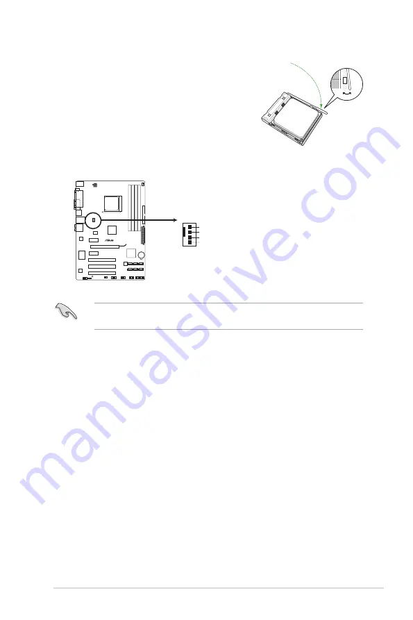
7.
Connect the CPU fan cable to the CPU_FAN connector on the motherboard.
DO NOT forget to connect the CPU fan connector! Hardware monitoring errors can occur if
you fail to plug this connector.
CPU_FAN
GND
CPU FAN PWR
CPU FAN IN
CPU FAN PWM
M4A77TD
M4A77TD CPU fan connector
ASUS M4A77TD
1-9
Summary of Contents for M4A77TD PRO U3S6
Page 1: ...Motherboard M4A77TD ...
Page 12: ...xii ...


