background image

ASUS M3N78-VM

1-15

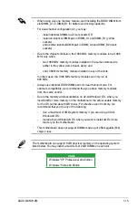
•  When using only one memory module, start installing the DDR2 DIMM from 

slot DIMM_A1 or DIMM_B1 for better overclocking capability. 

•  For dual-channel configuration (2), you may: 


-  install identical DIMMs in all four sockets OR  

-  install an identical DIMM pair in DIMM_A1 and DIMM_B1 (yellow  


sockets) 


and another identical DIMM pair in DIMM_A2 and DIMM_B2 (black   


sockets)

•  Due to the chipset’s limitation, the 1066 MHz memory modules run at 1066 

MHz only when:


-  two 1066 MHz memory modules installed in the same colored-slots   


(either in the yellow slots or black slots); and


-  one 1066 MHz memory module installed in any of the slots.

   In other cases, the 1066 MHz memory modules can only run at 


800 MHz. 


•  Always use identical DDR2 DIMM pairs for dual channel mode. For


optimum compatibility, we recommend that you obtain memory modules 

from the same vendor. 

•  Due to the memory address limitation on 32-bit Windows

®

 OS, when you 

install 4GB or more memory on the motherboard, the actual usable memory 

for the OS can be about 3GB or less. For effective use of memory, we 

recommend that you do any of the following:


-  Use a maximum of 3GB system memory if you are using a 32-bit


Windows® OS. 

-  Install a 64-bit Windows® OS when you want to install 4GB or more  


memory on the motherboard.

•  This motherboard does not support DIMMs made up of 256 megabits (Mb) 

chips or less.

64-bit

Windows

®

 XP Professional x64 Edition

Windows

®

 Vista x64 Edition

The motherboard can support 8 GB physical memory on the operating system 

listed below. You may install a maximum of 2 GB DIMMs on each slot.

Summary of Contents for M3N78-VM - Motherboard - Micro ATX

Page 1: ...Motherboard M3N78 VM ...

Page 2: ...ICULAR PURPOSE IN NO EVENT SHALL ASUS ITS DIRECTORS OFFICERS EMPLOYEES OR AGENTS BE LIABLE FOR ANY INDIRECT SPECIAL INCIDENTAL OR CONSEQUENTIAL DAMAGES INCLUDING DAMAGES FOR LOSS OF PROFITS LOSS OF BUSINESS LOSS OF USE OR DATA INTERRUPTION OF BUSINESS AND THE LIKE EVEN IF ASUS HAS BEEN ADVISED OF THE POSSIBILITY OF SUCH DAMAGES ARISING FROM ANY DEFECT OR ERROR IN THIS MANUAL OR PRODUCT SPECIFICATI...

Page 3: ...rection 1 9 1 5 3 Screw holes 1 9 1 6 Central Processing Unit CPU 1 10 1 6 1 Installing the CPU 1 10 1 6 2 Installing the heatsink and fan 1 12 1 7 System memory 1 14 1 7 1 Overview 1 14 1 7 2 Memory configurations 1 14 1 7 3 Installing a DIMM 1 18 1 7 4 Removing a DIMM 1 18 1 8 Expansion slots 1 19 1 8 1 Installing an expansion card 1 19 1 8 2 Configuring an expansion card 1 19 1 8 3 PCI slots 1 ...

Page 4: ... Configuration fields 2 14 2 2 7 Pop up window 2 14 2 2 8 Scroll bar 2 14 2 2 9 General help 2 14 2 3 Main menu 2 15 2 3 1 System Time 2 15 2 3 2 System Date 2 15 2 3 3 Legacy Diskette A 2 15 2 3 4 Primary IDE Master Slave SATA1 3 ESATA 2 16 2 3 5 Storage Configuration 2 18 2 3 6 System Information 2 19 2 4 Advanced menu 2 20 2 4 1 JumperFree Configuration 2 20 2 4 2 CPU Configuration 2 25 2 4 3 C...

Page 5: ...xpress Gate 2 42 2 7 3 AI NET 2 2 42 2 8 Exit menu 2 43 Chapter 3 Software support 3 1 Installing an operating system 3 2 3 2 Support DVD information 3 2 3 3 Creating a RAID driver disk 3 3 3 3 1 Creating a RAID driver disk without entering the OS 3 3 3 3 2 Creating a RAID driver disk in Windows 3 3 3 4 Software information 3 5 Chapter 4 NVIDIA technology support 4 1 NVIDIA Hybrid SLI Technology 4...

Page 6: ...ause harmful interference to radio or television reception which can be determined by turning the equipment off and on the user is encouraged to try to correct the interference by one or more of the following measures Reorient or relocate the receiving antenna Increase the separation between the equipment and receiver Connect the equipment to an outlet on a circuit different from that to which the...

Page 7: ...re installing the motherboard and adding devices on it carefully read all the manuals that came with the package Before using the product ensure that all cables are correctly connected and the power cables are not damaged If you detect any damage contact your dealer immediately To avoid short circuits keep paper clips screws and staples away from connectors slots sockets and circuitry Avoid dust h...

Page 8: ...through the BIOS Setup menus Detailed descriptions of the BIOS parameters are also provided Chapter 3 Software support This chapter describes the contents of the support CD DVD that comes with the motherboard package Chapter 4 NVIDIA technology support This chapter tells how to use the Hybrid SLI feature Where to find more information Refer to the following sources for additional information and f...

Page 9: ...ollow to complete a task Typography Bold text Indicates a menu or an item to select Italics Used to emphasize a word or a phrase Key Keys enclosed in the less than and greater than sign means that you must press the enclosed key Example Enter means that you must press the Enter or Return key Key1 Key2 Key3 If you must press two or more keys simultaneously the key names are linked with a plus sign ...

Page 10: ...x PCI Express x16 slot 1 x PCI Express TM x1 slot 2 x PCI slots Graphics Intergrated NVIDIA GeForce Series DirectX10 graphics processor Hybrid SLI support supports Windows Vista only Supports HDMI interface with HDCP compliant with max resolution up to 1920 x 1200 Supports DVI interface with HDCP compliant with max resolution up to 1600 x 1200 Supports D Sub with max resolution up to 1920 x 1440 7...

Page 11: ...CIe frequency tuning from 100 MHz to 200 MHz at 1 MHz increment Overclocking Protection ASUS CPU Parameter Recall C P R BIOS features 8 Mb Flash ROM AMI BIOS PnP DMI2 0 WfM2 0 SM BIOS 2 5 ACPI 2 0a Internal I O connectors 1 x High Definition front panel audio connector 1 x IDE connector 1 x Floppy disk drive connector 1 x CD audio in connector 1 x CPU fan connector 1 x Chassis fan connector 1 x Po...

Page 12: ...dio ports Support DVD contents Drivers Express Gate ASUS PC Probe II ASUS Update utility Anti virus software OEM version Accessories 2 x SATA cables 1 x 2 port SATA power cable 1 x UltraDMA 133 100 66 cable 1 x Floppy disk drive cable 1 x I O Shield User manual Form Factor MicroATX 9 6 in x 9 6 in 24 4 cm x 24 4 cm Specifications are subject to change without notice M3N78 VM specifications summary...

Page 13: ...1 Chapter 1 Product introduction This chapter describes the motherboard features and the new technologies it supports ...

Page 14: ...ables 2 x Serial ATA signal cables 1 x 2 port Serial ATA power cable 1 x Ultra DMA 133 100 cable 1 x Floppy disk drive cable Accessories I O shield Application DVD ASUS motherboard support DVD Documentation User guide AMD socket AM2 Phenom FX Phenom CPU The motherboard supports AMD socket AM2 multi core processors It features dual channel DDR2 1066 memory support and accelerates data transfer rate...

Page 15: ...DVI output It also supports HyperTransport TM 3 0 interface PCI Express TM 2 0 bus architecture Serial ATA 3 GB s devices and is optimized with AMD s latest AM2 and multi core CPUs to provide excellent system performance HDMITM Interface High Definiton Multimedia Interface HDMI is the first and only industry supported uncompressed all digital audio and video interface via a single cable and is HDC...

Page 16: ...nel HD audio High Definition Audio previously codenamed Azalia CODEC enables high quality 192KHz 24 bit audio output jack detect feature See page 1 24 and 1 25 for details HyperTransportTM 3 0 support HyperTransport 3 0 technology provides 2 6 times more bandwidth than HT1 0 that radically improves system efficiency for a smoother faster computing environment Hybrid SLITM Hybrid SLITM technology i...

Page 17: ...te the BIOS without using a bootable floppy disk or an OS based utility AI NET 2 ASUS AI NET2 remotely detects the cable connection immediately after turning on the system and any faulty cable connections are reported back up to 100 meters at 1 meter accuracy ASUS MyLogo 2 Turn your favorite photos into 256 color boot logos to personalize your system C P R CPU Parameter Recall The C P R feature of...

Page 18: ...nt friendly and recyclable products and packaging to safeguard consumers health while minimizing the impact on the environment Express Gate Express Gate is a unique OS built into the motherboard Five seconds after bootup you can instantly surf the Internet without entering the Windows OS The actual boot time depends on the system configuration ASUS Express Gate supports file uploading and download...

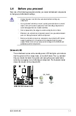
Page 19: ... from the wall socket before touching any component Use a grounded wrist strap or touch a safely grounded object or a metal object such as the power supply case before handling components to avoid damaging them due to static electricity Hold components by the edges to avoid touching the ICs on them Whenever you uninstall any component place it on a grounded antistatic pad or in the bag that came w...

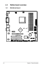
Page 20: ...B78 USB910 AAFP SB_PWR 8Mb BIOS Nvidia MCP78S DDR2 DIMM_A1 64 bit 240 pin module DDR2 DIMM_B1 64 bit 240 pin module DDR2 DIMM_A2 64 bit 240 pin module DDR2 DIMM_B2 64 bit 240 pin module CR2032 3V Lithium Cell CMOS Power PCI2 PCI1 PCIEX16 PCIEX1_1 VT1708B Realtek 8211CL GR CLRTC R SPDIF_OUT M3N78 VM LPT KB_USB56 VGA_DVI USB34_ESATA LAN1_USB12 AUDIO HDMI SPDIF_O2 CHA_FAN PWR_FAN FLOPPY CD TPM CHASSI...

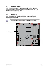
Page 21: ... motherboard ensure that you place it into the chassis in the correct orientation The edge with external ports goes to the rear part of the chassis as indicated in the image below 1 5 3 Screw holes Place eight screws into the holes indicated by circles to secure the motherboard to the chassis Place this side towards the rear of the chassis ...

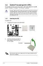
Page 22: ...PU is designed for the AM2 AM2 socket The CPU fits in only one correct orientation DO NOT force the CPU into the socket to prevent bending the connectors on the socket and damaging the CPU 1 6 1 Installing the CPU To install a CPU 1 Locate the CPU socket on the motherboard 2 Unlock the socket by pressing the lever sideways then lift it up to a 90 100 angle Ensure that the socket lever is lifted up...

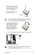
Page 23: ...he CPU 5 When the CPU is in place push down the socket lever to secure the CPU The lever clicks on the side tab to indicate that it is locked 6 Install a CPU heatsink and fan following the instructions that came with the heatsink package Gold triangle Small triangle 7 Connect the CPU fan cable to the CPU_FAN connector on the motherboard Do not forget to connect the CPU fan connector Hardware monit...

Page 24: ...acket Ensure that you use only qualified heatsink and fan assembly The retention module base is already installed on the motherboard upon purchase You do not have to remove the retention module base when installing the CPU or installing other motherboard components If you purchased a separate CPU heatsink and fan assembly make sure that a Thermal Interface Material is properly applied to the CPU h...

Page 25: ... lock to the retention module base A clicking sound denotes that the retention bracket is in place 4 Push down the retention bracket lock on the retention mechanism to secure the heatsink and fan to the module base Ensure that the fan and heatsink assembly perfectly fits the retention mechanism module base Otherwise you cannot snap the retention bracket in place ...

Page 26: ...40 pin footprint compared to the 184 pin DDR DIMM DDR2 DIMMs are notched differently to prevent installation on a DDR DIMM socket The figure illustrates the location of the DDR2 DIMM sockets Channel Sockets Channel A DIMM_A1 and DIMM_A2 Channel B DIMM_B1 and DIMM_B2 Recommended memory configurations Mode Sockets DIMM_A1 DIMM_B1 DIMM_A2 DIMM_B2 Single Channel Populated Populated Dual channel 1 Popu...

Page 27: ...an only run at 800 MHz Always use identical DDR2 DIMM pairs for dual channel mode For optimum compatibility we recommend that you obtain memory modules from the same vendor Due to the memory address limitation on 32 bit Windows OS when you install 4GB or more memory on the motherboard the actual usable memory for the OS can be about 3GB or less For effective use of memory we recommend that you do ...

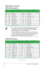
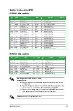
Page 28: ...00D2LL 1G N A Kingston DS Heat Sink Package 1G Samsung KR M378T2953CZ3 CE7 N A Samsung DS K4T51083QC ZCE7 1G Samsung KR M391T2953CZ3 CE7 N A Samsung DS K4T51083QC ZCE7 ECC 512MB Qimonda HYS64T64000EU 2 5 B2 6 Qimonda SS HYB18T512800B2F25FSS28380 1G Micron MT18HTF12872AY 80ED4 5 Micron DS 6TD22D9GKX ECC 1G Corsair XMS2 6400 5 Corsair DS Heat Sink Package 1G HY HYMP512U64AP8 S6 AA N A Hynix DS HY5PS...

Page 29: ...Nanya NT512T64U88A1BY 3C N A Nanya SS NT5TU64M8AE 3C 1G Kingtiger E0736001024667 N A Kingtiger DS KTG667PS6408NST C6 GDBTX DDR2 533 MHz capability Qualified Vendors Lists QVL DDR2 667 MHz capability Size Vendor Model CL Brand SS DS Component DIMM support A B C 512MB Kingston KVR533D2N4 512 N A Infineon SS HYB18T512800AF3733336550 512MB Samsung M378T6553BG0 CD5 4 Samsung SS K4T51083QB GCD5 1G HY HY...

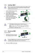
Page 30: ...y cause severe damage to both the motherboard and the components 1 7 4 Removing a DIMM To remove a DIMM 1 Simultaneously press the retaining clips outward to unlock the DIMM 2 Remove the DIMM from the socket Support the DIMM lightly with your fingers when pressing the retaining clips The DIMM might get damaged when it flips out with extra force A DDR2 DIMM is keyed with a notch so that it fits in ...

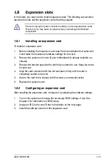
Page 31: ...p the screw for later use 4 Align the card connector with the slot and press firmly until the card is completely seated on the slot 5 Secure the card to the chassis with the screw you removed earlier 6 Replace the system cover 1 8 2 Configuring an expansion card After installing the expansion card configure it by adjusting the software settings 1 Turn on the system and change the necessary BIOS se...

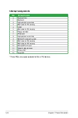
Page 32: ...d timer 1 Keyboard 2 High precision event timer 3 IRQ holder for PCI steering 4 COM1 5 IRQ holder for PCI steering 6 Floppy controller 7 Printer port 8 High precision event timer 9 AMD ACPI Compliant system 10 IRQ holder for PCI steering 11 IRQ holder for PCI steering 12 Microsoft PS 2 mouse 13 Numeric data processor 14 Primary IDE 15 Slave IDE ...

Page 33: ...UB11 LUB2 LUB0 LPMU LSMB LMAC LSA0 LAZA SGRU PCI slot1 shared PCI slot2 shared PCI EX1 Slot shared PCI EX16 slot shared Onboard USB1 1 OHCI shared Onboard USB 1 1 OHCI shared Onboard USB2 0 EHCI shared Onboard USB2 0 EHCI shared Onboard IDE controller shared Onboard SATA controller shared Onboard SMBus controller shared Onboard Azalia controller shared Onboard LAN 8111B shared Onboard PMU device s...

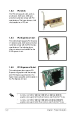
Page 34: ...press specifications The following figure shows a network card installed on the PCI Express x1 slot 1 8 5 PCI Express x16 slot This motherboard has supports PCI Express x16 graphic cards that comply with PCI Express specifications The figure shows a graphics card installed on the PCI Express x16 slot Currently only NVIDIA GeForce 8500 GT and GeForce 8400 GS graphics cards support GeForce Boost fun...

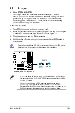
Page 35: ...Plug the power cord and turn ON the computer 4 Hold down the Del key during the boot process and enter BIOS setup to re enter data Except when clearing the RTC RAM never remove the cap on CLRTC jumper default position Removing the cap will cause system boot failure If the steps above do not help remove the onboard battery and move the jumper again to clear the CMOS RTC RAM data After clearing the ...

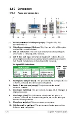
Page 36: ...ts the side speakers in an 8 channel audio configuration Activity Link LED Speed LED Status Description Status Description OFF No link OFF 10 Mbps connection ORANGE Linked ORANGE 100 Mbps connection BLINKING Data activity GREEN 1 Gbps connection LAN port LED indications SPEED LED ACT LINK LED LAN port 1 PS 2 keyboard mouse combo port purple This port is for a PS 2 keyboard or mouse 2 Video Graphic...

Page 37: ...o ports in 2 4 6 or 8 channel configuration To use hot plug set the SATA Mode Select in the BIOS settings to AHCI Mode See section 2 3 5 Storage Configuration for details When the AHCI mode is turned on SATA 1 2 3 5 6 and eSATA are all in AHCI mode and DOS cannot detect HDD in drivers installation 13 DVI port This port is for any DVI D compatible device DVI D can t be converted to output RGB Signa...

Page 38: ...k quality Using the CPU Memory of higher speed and bandwidth with the higher version DVD player and drivers will upgrade the playback quality 15 Coaxial S PDIF Out port This port connects an external audio output device via a coaxial S PDIF cable 16 USB 2 0 ports 5 and 6 These two 4 pin Universal Serial Bus USB ports are available for connecting USB 2 0 devices ...

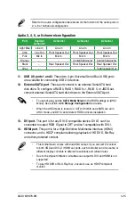
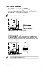
Page 39: ...Pin 5 2 TPM connector 20 1 pin TPM This connector supports a Trusted Platform Module TPM system which can securely store keys digital certificates passwords and data A TPM system also helps enhance network security protects digital identities and ensures platform integrity The TPM model is purchased separately R M3N78 VM M3N78 VM Floppy Disk Drive Connector NOTE Orient the red markings on the flop...

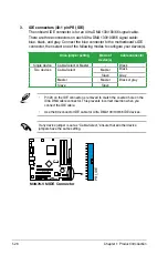
Page 40: ...in 20 on the IDE connector is removed to match the covered hole on the Ultra DMA cable connector This prevents incorrect insertion when you connect the IDE cable Use the 80 conductor IDE cable for Ultra DMA 133 100 66 IDE devices If any device jumper is set as Cable Select ensure that all other device jumpers have the same setting Drive jumper setting Mode of device s Cable connector Single device...

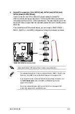
Page 41: ... Service Pack 1 before using Serial ATA For detailed instructions on how to configure RAID 0 RAID 1 RAID 5 and RAID 0 1 and JBOD refer to the RAID manual in the support DVD If you intend to create a Serial ATA RAID set using these connectors set the SATA Mode select item in the BIOS to RAID Mode See the page 2 18 for details Due to the chipset limitation SATA 4 and SATA 5 do not support IDE mode o...

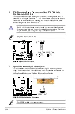
Page 42: ...Sony Philips Digital Interface S PDIF port s Connect the S PDIF module cable to this connector then install the module to a slot opening at the back of the system chassis Only CPU Fan supports Q Fan The S PDIF module is purchased separately Do not forget to connect the fan cables to the fan connectors Insufficient air flow inside the system may damage the motherboard components These are not jumpe...

Page 43: ...ctors Doing so will damage the motherboard 8 Optical drive audio in connector 4 pin CD These connectors allow you to receive stereo audio input from sound sources such as a CD ROM TV tuner or MPEG card The USB 2 0 module is purchased separately R M3N78 VM M3N78 VM USB 2 0 Connectors USB78 USB 5V USB_P8 USB_P8 GND NC USB 5V USB_P7 USB_P7 GND 1 USB910 USB 5V USB_P10 USB_P10 GND NC USB 5V USB_P9 USB_...

Page 44: ...definition front panel audio module to this connector to avail of the motherboard high definition audio capability If you want to connect a high definition front panel audio module to this connector ensure that the Front Panel Select item in the BIOS is set to HD Audio if you want to connect an AC 97 front panel audio module to this connector set the item to AC97 See page 2 29 for details The seri...

Page 45: ...n event By default the pin labeled Chassis Signal and Ground are shorted with a jumper cap Remove the jumper caps only when you intend to use the chassis intrusion detection feature 12 LPT connector The LPT Line Printing Terminal connector supports devices such as a printer LPT standardizes as IEEE 1284 which is the parallel port interface on IBM PC compatible computers R M3N78 VM M3N78 VM Paralle...

Page 46: ...boot up if the power is inadequate Do not forget to connect the 4 pin ATX 12 V power plug Otherwise the system will not boot up We recommend that you use a PSU with higher power output when configuring a system with more power consuming devices The system may become unstable or may not boot up if the power is inadequate If you are uncertain about the minimum power supply requirement for your syste...

Page 47: ...the HDD System warning speaker 4 pin SPEAKER This 4 pin connector is for the chassis mounted system warning speaker The speaker allows you to hear system beeps and warnings Power Soft off button 2 pin PWRSW This 2 pin connector is for the system power button Pressing the power button turns the system ON or puts the system in SLEEP or SOFT OFF mode depending on the BIOS settings Pressing the power ...

Page 48: ...2 This chapter tells how to change the system settings through the BIOS Setup menus Detailed descriptions of the BIOS parameters are also provided Chapter 2 BIOS setup ...

Page 49: ...etails on these utilities Save a copy of the original motherboard BIOS file to a bootable floppy disk in case you need to restore the BIOS in the future Copy the original motherboard BIOS using the ASUS Update or AFUDOS utilities 2 1 1 Creating a bootable floppy disk 1 Do either one of the following to create a bootable floppy disk DOS environment a Insert a 1 44MB floppy disk into the drive b At ...

Page 50: ... disk drive b Click from the Windows desktop then select Computer c Right click Floppy Disk Drive then click Format to display the Format 3 1 2 Floppy dialog box d Select the Create an MS DOS startup disk check box e Click Start 2 Copy the original or the latest motherboard BIOS file to the bootable floppy disk ...

Page 51: ...press Enter to enable it You can switch between drives by pressing Tab before the correct file is found Then press Enter 4 When the correct BIOS file is found EZ Flash 2 performs the BIOS update process and automatically reboots the system when done 1 Insert the floppy disk USB flash disk that contains the BIOS file to the floppy disk drive or the USB port Press Alt F2 during POST to display the f...

Page 52: ...hen at the prompt type afudos o filename where the filename is any user assigned filename not more than eight alphanumeric characters for the main filename and three alphanumeric characters for the extension name A afudos oOLDBIOS1 rom Ensure that the floppy disk is not write protected and has at least 1024KB free space to save the file The succeeding BIOS screens are for reference only The actual...

Page 53: ...ase restart your computer A 2 Copy the AFUDOS utility afudos exe from the motherboard support DVD to the bootable floppy disk you created earlier 3 Boot the system in DOS mode then at the prompt type afudos i filename where filename is the latest or the original BIOS file on the bootable floppy disk A afudos iM3N78VM ROM Write the BIOS filename on a piece of paper You need to type the exact BIOS f...

Page 54: ...flash disk to M3N78VM ROM Recovering the BIOS from a floppy disk To recover the BIOS from a floppy disk 1 Turn on the system 2 Insert the floppy disk with the original or updated BIOS file to the floppy disk drive 3 The utility displays the following message and automatically checks the floppy disk for the original or updated BIOS file Bad BIOS checksum Starting BIOS recovery Checking for floppy W...

Page 55: ...tarting BIOS recovery Checking for floppy 4 Restart the system after the utility completes the updating process The recovered BIOS may not be the latest BIOS version for this motherboard Visit the ASUS website www asus com to download the latest BIOS file Only the USB flash disk with FAT 32 16 format and single partition can support ASUS CrashFree BIOS 3 The device size should be smaller than 8GB ...

Page 56: ...ge save and update the motherboard BIOS in Windows environment The ASUS Update utility allows you to Save the current BIOS file Download the latest BIOS file from the Internet Update the BIOS from an updated BIOS file Update the BIOS directly from the Internet and View the BIOS version information This utility is available in the support DVD that comes with the motherboard package ASUS Update requ...

Page 57: ... Next Updating the BIOS through the Internet To update the BIOS through the Internet 1 Launch the ASUS Update utility from the Windows desktop by clicking Start Programs ASUS ASUSUpdate ASUSUpdate The ASUS Update main window appears 2 Select Update BIOS from the Internet option from the drop down menu then click Next ...

Page 58: ... a file option from the drop down menu then click Next 3 Locate the BIOS file from the Open window then click Open 4 Follow the screen instructions to complete the update process 4 From the FTP site select the BIOS version that you wish to download Click Next 5 Follow the screen instructions to complete the update process The ASUS Update utility is capable of updating itself through the Internet A...

Page 59: ...If you wish to enter Setup after POST reboot the system by doing any of the following procedures Restart using the OS standard shut down procedure Press Ctrl Alt Del simultaneously Press the reset button on the system chassis Press the power button to turn the system off then back on The default BIOS settings for this motherboard apply for most conditions to ensure optimum performance If the syste...

Page 60: ...advanced system settings Power For changing the advanced power management APM configuration Boot For changing the system boot configuration Tools For setting EZ Flash 2 Exit For selecting the exit options and loading default settings To select an item on the menu bar press the right or left arrow key on the keyboard until the desired item is highlighted Use ENTER TAB or SHIFT TAB to select a field...

Page 61: ...n is a brief description of the selected item Some of the navigation keys differ from one screen to another 2 2 7 Pop up window Select a menu item then press Enter to display a pop up window with the configuration options for that item 2 2 8 Scroll bar A scroll bar appears on the right side of a menu screen when there are items that do not fit on the screen Press the Up Down arrow keys or Page Up ...

Page 62: ...y xx xx xxxx Allows you to set the system date 2 3 3 Legacy Diskette A 1 44M 3 5 in Sets the type of floppy drive installed Configuration options Disabled 360K 5 25 in 1 2M 5 25 in 720K 3 5 in 1 44M 3 5 in 2 88M 3 5 in System Time 03 30 50 System Date Mon 01 28 2002 Legacy Diskette A 1 44M 3 5 in Primary IDE Master Not Detected Primary IDE Slave Not Detected SATA1 ST380011AS SATA2 Not Detected SAT...

Page 63: ...A Mode Block Mode PIO Mode Async DMA Ultra DMA and SMART monitoring These values are not user configurable These items show N A if no IDE device is installed in the system Type Auto Selects the type of IDE drive Setting to Auto allows automatic selection of the appropriate IDE device type Select CDROM if you are specifically configuring a CD ROM drive Select ARMD ATAPI Removable Media Device if yo...

Page 64: ...to PIO Mode Auto Selects the PIO mode Configuration options Auto 0 1 2 3 4 DMA Mode Auto Selects the DMA mode Configuration options Auto SMART Monitoring Auto Enables or disables the S M A R T Self Monitoring and Reporting Technology capability of your hard drive This features allows your system to report read write errors of the hard drive and to issue warnings when a third party hardware monitor...

Page 65: ...ATA Mode Allows you to select the SATA Mode Configuration options SATA Mode RAID Mode AHCI Mode 2 3 5 Storage Configuration The items in this menu allow you to set or change the configurations for the IDE devices installed in the system Select an item then press Enter if you wish to configure the item IDE Configuration Onboard PCI IDE Controller Enabled OnChip S ATA Controller Enabled SATA Mode se...

Page 66: ...he items in this menu AMIBIOS Version 0509 Build Date 07 07 08 Processor Type AMD Sempron tm Processor 3200 Speed 1800MHz Count 1 System Memory Installed Size 1024MB Usable Size 896MB AMI BIOS Displays the auto detected BIOS information Processor Displays the auto detected CPU specification System Memory Displays the auto detected system memory ...

Page 67: ...tion Configure System Frequency Voltage CPU Overclocking Auto GPU Overclocking Auto PCIE Overclocking Auto CPU Ratio and Voltage Processor Frequency Multiplier Auto Processor Voltage Auto Processor NB Voltage Auto Hyper Transport Configuration Hyper Transport Speed Auto Hyper Transport Width 16 16 Memory Timing and Voltage Memory Clock Mode Auto DRAM Timing Mode Auto Memory Over voltage Auto Selec...

Page 68: ...en the CPU Overclocking item is set to Overclock Profile Overclock Options Auto Allows you to select the overclock options Configuration options Auto Overclock 3 Overclock 5 Overclock 7 Test mode GPU OverClocking Auto Allows selection of GPU overclocking options to achieve desired GPU frequency Select either one of the preset overclocking configuration options Auto allows you to set overclocking p...

Page 69: ... Auto Allows you to select the processor frequency multiplier Configuration options Auto x4 0 800MHz x5 0 1000MHz x6 0 1200MHz x7 0 1400MHz x8 0 1600MHz x9 0 1800MHz Processor Voltage Auto Allows you to select the processor voltage Configuration options Auto 50mv 100mv 150mv Processor NB Voltage Auto Allows you to select the processor NB voltage Configuration options Auto 50mv 100mv 150mv Hyper Tr...

Page 70: ...ons 3 CLK 4 CLK 5 CLK 6 CLK Auto TRP Auto Allows you to set TRP Configuration options 3 CLK 4 CLK 5 CLK 6 CLK Auto tRTP Auto Allows you to specify the read CAS to percharge time Configuration options Auto 2 4 CLK 3 5 CLK TRAS Auto Allows you to set TRAS Configuration options 5 CLK 6 CLK 7 CLK 8 CLK 9 CLK 10 CLK 11 CLK 12 CLK 13 CLK 14 CLK 15 CLK 16 CLK 17 CLK 18 CLK Auto TRC Auto Allows you to set...

Page 71: ...3 CLK Auto tWRWR Auto Allows you to specify the Twrwr time Configuration options Auto 1 CLK 2 CLK 3 CLK tRDRD Auto Allows you to specify the Trdrd time Configuration options Auto 2 CLK 3 CLK 4 CLK 5 CLK tRFC0 1 2 3 Auto Allows you to specify the Trfc0 1 2 3 time Configuration options Auto 75ns 105ns 127 5ns 195ns 327 5ns Memory Over Voltage Auto Allows you to select the Memory Over Voltage The inc...

Page 72: ...ed Enabled Cool n Quiet Enabled Allows you to enable or disable the generation of ACPI_PPC _PSS and _PCT objects Configuration options Disabled Enabled This option should remain disabled for the normal operation The driver developer may enable it for testing purpose CPU Configuration Module Version 13 20 AGESA Version 3 1 8 0 Physical Count 1 Logical Count 1 AMD Athlon tm Processor 3200 Revision F...

Page 73: ...guration 2 4 3 Chipset The Chipset menu allows you to change the advanced chipset settings Select an item then press Enter to display the sub menu Advanced Chipset Setting WARNING Setting wrong values in below sections may cause system to malfunction NorthBridge Configuration Southbridge Configuration Options for NB ...

Page 74: ...nfiguration options Disabled Address bits 6 Address bits 12 XOR of Address bits 20 16 6 XOR of Address bits 20 16 9 Enable Clock to All DIMMs Disabled Enables or disables clock to all DIMMs Configuration options Disabled Enabled MemClk Tristate C3 ALTVID Disabled Enables or disables the MemClk Tristate C3 ALTVID Configuration options Disabled Enabled Memory Hole Remapping Enabled Enables or disabl...

Page 75: ...M BG Scrub Disabled Disables or sets the DRAM BG Scrub Configuration options Disabled 40ns 80ns 160ns 320ns 640ns 1 28us 2 56us 5 12us 10 2us 20 5us 41 0us 81 9us 163 8us 327 7us 655 4us 1 31ms 2 62ms 5 24ms 10 49ms 20 97ms 42 00ms 84 00ms Data L2 L3 Cache BG Scrub Disabled Disables or sets the Data L2 L3 Cache BG Scrub This item allows the cache RAM to be corrected when idle Configuration options...

Page 76: ...io Internal codec External codec Allows you to set HD Audio mode Configuration options Disabled Internal codec External codec Internal codec External codec Front Panel Select HD Audio Allows you to set HD Audio mode Configuration options AC97 HD Audio Onboard LAN Enabled Allows you to set or disable the Onboard LAN Configuration options Enabled Disabled SouthBridge Configuration SouthBridge chipse...

Page 77: ...r Serial Port1 Configuration options Normal IrDA ASK IR Parallel Port Address 378 Allows you to select the Parallel Port base addresses Configuration options Disabled 378 278 3BC Parallel Port Mode Normal Allows you to select the Parallel Port mode Configuration options Normal EPP ECP EPP ECP Allows BIOS to select Serial Port1 Base Address OnBoard LAN Boot ROM Disabled Allows you to enable or disa...

Page 78: ... Play O S No When set to No BIOS configures all the devices in the system When set to Yes and if you install a Plug and Play operating system the operating system configures the Plug and Play devices not required for boot Configuration options No Yes PCI Latency Timer 64 Allows you to select the value in units of PCI clocks for the PCI device latency timer register Configuration options 32 64 96 1...

Page 79: ...nce of USB devices at startup If detected the USB controller legacy mode is enabled If no USB device is detected the legacy USB support is disabled Configuration options Disabled Enabled Auto USB 2 0 Controller Mode HiSpeed Allows you to configure the USB 2 0 controller in HiSpeed 480 Mbps or Full Speed 12 Mbps Configuration options Full Speed HiSpeed The Module Version and USB Devices Enabled ite...

Page 80: ...Computing related settings Select an item then press Enter to display the configuration options Trusted Computing TCG TPM SUPPORT No Enable Disable TPM TCG TPM 1 1 1 2 supp in BIOS TCG TPM SUPPORT No Allows you to enable or disable the TPM TCG TPM 1 1 1 2 support in BIOS Configuration options No Yes ...

Page 81: ...end to RAM sleep state default In S3 sleep state the system appears to be off and consumes less power than in the S1 state When signaled by a wake up device or event the system resumes to its working state exactly where it was left off Auto Detected by OS 2 5 2 ACPI 2 0 Support Disabled Allows you to add additional tables as per Advanced Configuration and Power Interface ACPI 2 0 specifications Co...

Page 82: ...o enable or disable PCI PCIE Onboard LAN devices to generate a wake event Configuration options Disabled Enabled Power On By Ring Disabled Allows you to enable or disable RI to generate a wake event Configuration options Disabled Enabled Power On By PS 2 KB MS Disabled Allows you to enable or disable PS 2 Keyboard Mouse to generate a wake event Configuration options Disabled Enabled Power On By RT...

Page 83: ... in rotations per minute RPM If the fan is not connected to the motherboard the field shows N A Select Ignored if you do not wish to display the detected speed Chassis Power Fan Speed xxxxRPM or N A or Ignored The onboard hardware monitor automatically detects and displays the chassis power fan speed in rotations per minute RPM If the fan is not connected to the chassis the specific field shows N ...

Page 84: ...lect Screen Select Item Change Option F1 General Help F10 Save and Exit ESC Exit 2 6 1 Boot Device Priority Boot Device Priority 1st Boot Device 1st FLOPPY DRIVE 2nd Boot Device SATA 3M ST380011AS 3rd Boot Device CDROM PS PIONEER D 1st xxth Boot Device 1st Floppy Drive These items specify the boot device priority sequence from the available devices The number of device items that appears on the sc...

Page 85: ...ystem When set to Disabled BIOS performs all the POST items Configuration options Disabled Enabled Full Screen Logo Enabled This allows you to enable or disable the full screen logo display feature Configuration options Disabled Enabled Add On ROM Display Mode Force BIOS Sets the display mode for option ROM Configuration options Force BIOS Keep Current Bootup Num Lock On Allows you to select the p...

Page 86: ... to change password Enter again to disabled password Change Supervisor Password Select this item to set or change the supervisor password The Supervisor Password item on top of the screen shows the default Not Installed After you set a password this item shows Installed To set a Supervisor Password 1 Select the Change Supervisor Password item and press Enter 2 From the password box type a password...

Page 87: ...he password box that appears type a password composed of at least six letters and or numbers then press Enter 3 Confirm the password when prompted The message Password Installed appears after you set your password successfully To change the user password follow the same steps as in setting a user password Clear User Password Select this item to clear the user password Password Check Setup When set...

Page 88: ...arrow key to select between Yes or No then press Ok to confirm your choice ASUSTek EZ Flash 2 BIOS ROM Utility V3 21 Current ROM Update ROM A Note Enter Select or Load Tab Switch V Drive Info Up Down Home End Move B Backup Esc Exit FLASH TYPE MXIC 25L8005 PATH A BOARD M3N78 VM VER 0509 H 01 B 17 DATE 07 07 2008 BOARD Unknown VER Unknown DATE Unknown Press ENTER to run the utility to select and upd...

Page 89: ...ser data Configuration options No Reset When setting this item to Reset the user data is cleared the next time you enter the Express Gate User data includes the Express Gate s settings as well as any personal information stored by the web browser such as bookmarks cookies or browsing history This is useful in the rare case where corrupt settings prevent the Express Gate environment from launching ...

Page 90: ... RAM Exit Save Changes Once you are finished making your selections choose this option from the Exit menu to ensure the values you selected are saved to the CMOS RAM An onboard backup battery sustains the CMOS RAM so it stays on even when the PC is turned off When you select this option a confirmation window appears Select OK to save changes and exit 2 8 Exit menu Pressing Esc does not immediately...

Page 91: ...3 Chapter 3 Software support This chapter describes the contents of the support DVD that comes with the motherboard package ...

Page 92: ...ility and system stability 3 2 Support DVD information The support DVD that comes with the motherboard package contains the drivers software applications and utilities that you can install to avail all motherboard features The contents of the support DVD are subject to change at any time without notice Visit the ASUS website http www asus com for updates Click an item to install Running the suppor...

Page 93: ...AID driver disk 8 Insert a formatted floppy disk into the floppy drive then press Enter 9 Follow succeeding screen instructions to complete the process 3 3 2 Creating a RAID driver disk in Windows To create a RAID driver disk in Windows 1 Start Windows 2 Place the motherboard support DVD into the optical drive 3 Go to the Make Disk menu then click NVIDIA 32 64bit XP SATA RAID Driver to create a NV...

Page 94: ...ed Insert Disk1 when you see the following instruction in Windows Setup DO NOT remove Disk1 until you are asked to insert Disk2 Remove Disk1 and insert Disk2 when you see the following instruction in Windows XP Setup Follow the succeeding screen instructions to complete the setup Insert the disk labeled NVIDIA RAID DRIVER SCSI disk 2 into Drive A Press ENTER when ready Windows XP Professional Setu...

Page 95: ...ironment that gives you quick access to the Internet Skype and viewing your pictures Within a few seconds of powering on your computer you will be at the Express Gate menu where you can start the web browser Skype or other Express Gate applications Installing ASUS Express Gate ASUS Express Gate supports installation on SATA HDDs in IDE mode only See the chapter of BIOS setup in your motherboard us...

Page 96: ...a few seconds after you power on the computer Click any of the application icons to enter Express Gate environment and launch the selected application Turn off the computer Enter motherboard BIOS setup Continue booting to existing OS when timer counts down to zero 0 click to immediately enter existing OS Knowing the Express Gate hot keys Here is a list of common used hot keys for Express Gate In t...

Page 97: ... on Skype for free as well as offering affordable high quality voice communications to phones all over the world Opens Configuration Panel which lets you specify network settings and other preferences A red mark under an application icon denotes that the application is already running In the rare case that one of the above applications stops responding you can right click on its icon and then sele...

Page 98: ...re network settings To configure network settings 1 Click Configuration Panel in the LaunchBar 2 In the Configuration Panel click Network 3 Make the proper network configurations Each network interface is enabled immediately when you check the box next to it LAN settings If you use a network cable connected to a home router which is then connected to your DSL cable modem enable every LAN port s Ex...

Page 99: ...Cable dial up PPPoE settings If you use a network cable connected directly to your DSL cable modem no router in between click Setup for xDSL cable dial up Choose whether the DSL cable modem is connected to your computer s LAN port Then enter the user name and password of your dial up account Click OK to enable xDSL cable dial up and establish the PPPoE connection When PPPoE is enabled the port it ...

Page 100: ...ar View mode selection Help Photo slideshow ASUS Express Gate supports HDDs or ODDs connected to motherboard chipset controlled onboard SATA ports only All onboard extended SATA ports and external SATA ports are NOT supported Restoring to factory settings In the rare case that the system settings become corrupted you can restore Express Gate to its factory settings To restore Express Gate to facto...

Page 101: ...ASUS support website To update Express Gate 1 Double click the Express Gate setup file to start application update 2 A application update confirmation dialog box appears Click Yes to continue 3 The InstallShield Wizard for Express Gate appears Click Next to continue 4 Follow the screen instructions to complete installation BIOS SETUP UTILITY Main Ai Tweaker Advanced Power Boot Tools Exit ASUS EZ F...

Page 102: ...4 Chapter 4 NVIDIA technology support This chapter tells how to use the Hybrid SLI feature ...

Page 103: ...ended for GeForce Boost At least 256MB of Frame Buffer carve out for the motherboard GPU For best HybridPower benefits AMD Athlon X2 3800 CPU operating at 1800Mhz or higher 2 x 1024MB of DDR2 667 DRAM Discrete GPU recommended for HybridPower At least 256MB of Frame Buffer carve out for the motherboard GPU Hybrid SLI technology is supported by Windows Vista only GeForce Boost supports up to two dis...

Page 104: ... Auto AZALIA Audio Internal codec E Front Panel Select HD Audio Onboard LAN Auto OnBoard LAN Boot ROM Disabled SouthBridge ACPI HPET TABLE Enabled Options PCI VGA Card First Internal VGA First PCIE VGA Card First 3 Save your changes and Exit Setup 4 Turn off the system disconnect your display from the dGPU and connect your display to the onboard VGA port at the rear panel 5 Turn on the system and ...

Page 105: ...erformance of the dGPU 12 Click the Hybrid SLI icon and select Save Power item 13 The icon will change state from to to indicate that the system is in Power Saving mode which means that the dGPU is turned off and the mGPU is both rendering and displaying 14 When the Power Saving mode is enabled the dGPU does not show in the Windows Device Manager 7 Save your changes and Exit Setup 8 From the Windo...

Reviews: