


3-42
Chapter 3: BIOS setup
Chapter 3
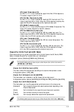
Chassis Fan 1/2/3 Upper Temperature [70]
Use the <+> or <-> keys to adjust the upper limit of the chassis
temperature. The values range from 40
°
C to 90
°
C.
Chassis Fan 1/2/3 Max. Duty Cycle(%) [100]
Use the <+> or <-> keys to adjust the maximum chassis fan duty cycle. The
values range from 20% to 100%. When the chassis temperature reaches
the upper limit, the chassis fan will operate at the maximum duty cycle.
Chassis Fan 1/2/3 Middle Temperature [45]
Use the <+> or <-> keys to set the value for Chassis Fan Middle
Temperature.
Chassis Fan 1/2/3 Middle Duty Cycle(%) [60]
Use the <+> or <-> keys to adjust the chassis fan middle duty cycle. The
values range from 20% to 100%.
Chassis Fan 1/2/3 Lower Temperature [40]
Use the <+> or <-> keys to adjust the chassis fans’ lower temperature. The
values range from 20% to 75%.
Chassis Fan 1/2/3 Min. Duty Cycle(%) [60]
Use the <+> or <-> keys to adjust the minimum chassis fan duty cycle. The
values range from 20% to 100%. When the chassis temperature is under
40
°
C, the chassis fan operates at the minimum duty cycle.
Allow Fan Stop [Disabled]
This item appears only when you set
Chassis Fan 1/2/3 Profile
to [Manual] and allows
your fans to run at 0% duty cycle when the temperature of the source drops below the lower
temperature. Configuration options: [Disabled] [Enabled]
Anti-Surge Support [Enabled]
This item allows you to enable or disable the OVP (Over Voltage Protection) and UVP (Under
Voltage Protection) functions. This causes the system to automatically shut down when the
voltage exceeds the safe range that protects the motherboard’s components.
Configuration options: [Disabled] [Enabled]
Summary of Contents for H-97-PRO
Page 1: ...Motherboard H97 PRO ...
Page 38: ...1 24 Chapter 1 Product introduction Chapter 1 ...
Page 43: ...ASUS H97 PRO 2 5 Chapter 2 To uninstall the CPU heatsink and fan assembly ...
Page 44: ...2 6 Chapter 2 Basic installation Chapter 2 To remove a DIMM 2 1 4 DIMM installation ...
Page 45: ...ASUS H97 PRO 2 7 Chapter 2 2 1 5 ATX Power connection OR ...
Page 46: ...2 8 Chapter 2 Basic installation Chapter 2 2 1 6 SATA device connection OR OR ...
Page 54: ...2 16 Chapter 2 Basic installation Chapter 2 ...
Page 134: ...4 22 Chapter 4 Software support Chapter 4 ...
Page 148: ...A 6 Appendices Appendices ...