


3-18
Chapter 3: BIOS setup
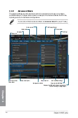
Chapter 3
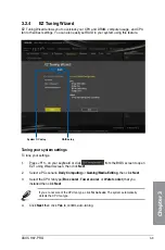
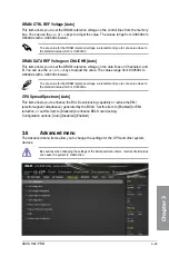
DIGI+ VRM
CPU Load-line Calibration [Auto]
Load-line is defined by Intel VRM spec and affects CPU voltage. The CPU working
voltage will decrease proportionally to CPU loading. Higher value gets a higher voltage
and better overclocking performance, but increases the CPU and VRM thermal.
Configuration options: [Auto] [Regular] [Medium] [High] [Ultra High] [Extreme]
The actual performance boost may vary depending on your CPU specification.
DO NOT remove the thermal module. The thermal conditions should be monitored.
CPU VRM Switching Frequency [Auto]
This item affects the VRM transient response speed and the component thermal
production. Select [Manual] to configure a higher frequency for a quicker transient
response speed.
Configuration options: [Auto] [Manual]
DO NOT remove the thermal module. The thermal conditions should be monitored.
The following item appears only when you set the CPU VRM Switching Frequency to
[Manual]
.
Fixed CPU VRM Switching Frequency (KHz) [250]
This item allows you to set a higher frequency for a quicker transient
response speed. Use the <+> or <-> to adjust the value. The values range
from 200 KHz to 350 KHz with an interval of 50 KHz.
CPU Power Phase Control [Auto]
This item allows you to set the power phase control of the CPU.
Configuration options: [Auto] [Standard] [Optimized] [Extreme] [Power Phase
Response]
DO NOT remove the thermal module when setting this item to
[Power Phase Response]
.
The thermal conditions should be monitored.
The following item appears only when you set the CPU Power Phase Control to
[Power
Phase Response]
.
Power Phase Response [Fast]
This item allows you to set a faster phase response for the CPU to increase
system performance or to slower phase response to decrease DRAM
power efficiency.
Configuration options: [Ultra Fast] [Fast] [Medium] [Regular]
Summary of Contents for H-97-PRO
Page 1: ...Motherboard H97 PRO ...
Page 38: ...1 24 Chapter 1 Product introduction Chapter 1 ...
Page 43: ...ASUS H97 PRO 2 5 Chapter 2 To uninstall the CPU heatsink and fan assembly ...
Page 44: ...2 6 Chapter 2 Basic installation Chapter 2 To remove a DIMM 2 1 4 DIMM installation ...
Page 45: ...ASUS H97 PRO 2 7 Chapter 2 2 1 5 ATX Power connection OR ...
Page 46: ...2 8 Chapter 2 Basic installation Chapter 2 2 1 6 SATA device connection OR OR ...
Page 54: ...2 16 Chapter 2 Basic installation Chapter 2 ...
Page 134: ...4 22 Chapter 4 Software support Chapter 4 ...
Page 148: ...A 6 Appendices Appendices ...