4
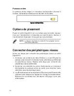
Rear Panel
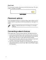
The rear panel includes a three-prong universal power plug. The input
power is 100-240V AC /50-60Hz.
Figure 3. Rear panel
Placement options
Place the GigaX1016 Switch on a flat and stable surface. Make sure the
location meets the operating environment specifications. See page 6 for
details.
NOTE:
The maximum cable length of UTP Category 5 is 100 meters
(328 feet).
Connecting network devices
Follow these steps to connect network devices to the GigaX1016 Switch:
1. Connect one end of the Ethernet cable to an Ethernet port on the Switch
front panel. Connect the other end to the Ethernet port of the network
device. Repeat this step to connect additional network devices.
2. Plug one end of the power cable to the power connector on the Switch
rear panel, then plug the other end to an electrical outlet.
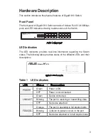
3. The Power LED and LED indicators for active Ethernet ports light up to
indicate that the device is on and in use. Refer to the LED table in page
3 for indications.
Summary of Contents for GigaX 1016
Page 2: ...1 GigaX 1016 User Guide Copyright 2005 ASUSTeK COMPUTER INC All Rights Reserved ...
Page 8: ...7 GigaX 1016 Guide Copyright 2005 ASUSTeK COMPUTER INC Tous droits réservés ...
Page 14: ...13 GigaX 1016 Benutzerhandbuch Copyright 2005 ASUSTeK COMPUTER INC Alle Rechte vorbehalten ...
Page 32: ...31 GigaX 1016 Guida dellʼutente Copyright 2005 ASUSTeK COMPUTER INC Tutti i diritti riservati ...
Page 38: ...37 GigaX 1016 Kullanıcı Kılavuzu Telif Hakkı 2005 ASUSTeK COMPUTER INC Tüm Hakları Saklıdır ...
Page 44: ...43 GigaX 1016 用户手册 版权所有 不得翻印 2005 华硕电脑 ...
Page 50: ...49 GigaX 1016 사용자 설명서 Copyright 2005 ASUSTeK COMPUTER INC All Rights Reserved ...
Page 56: ...55 GigaX 1016 ユーザーマニュアル Copyright 2005 ASUSTeK COMPUTER INC All Rights Reserved ...
Page 62: ...GigaX 1016 61 Copyright 2005 ASUSTek COMPUTER INC All Rights Reserved ...
Page 65: ...64 100 240V AC 50 60Hz GigaX1016 P 6 UTP Category 5 100 328 3 GigaX1016 1 2 3 LED P 3 LED ...


