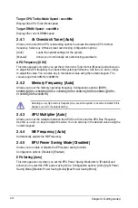
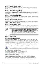
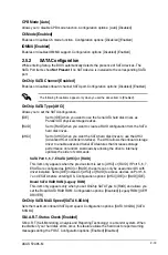
background image

ASUS F2A85-M

2-25

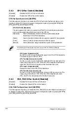
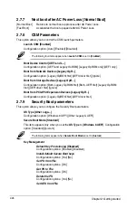
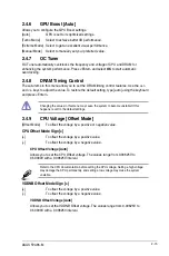
CHA_FAN Fan Profile [Standard]

This item appears only when you enable the 

CHA_FAN Q-Fan Control

 feature and 

allows you to set the appropriate performance level of the CHA_FAN fan.

[Standard] 

Sets to [Standard] to make the chassis fan automatically adjust 

depending on the chassis temperature.

[Silent] 

Sets to [Silent] to minimize the fan speed for quiet chassis fan 

operation.

[Turbo] 

Sets to [Turbo] to achieve maximum chassis fan speed.

[Manual] 

Sets to [Manual] to assign detailed fan speed control parameters.

The following four items appear only when you set 

CHA_FAN Fan Profile

 to [Manual].

CHA_FAN Upper Temperature [70]

Use the <+> and <-> keys to adjust the upper limit of the chassis 

temperature. The values range from 20ºC to 90ºC. 

CHA_FAN Fan Max. Duty Cycle(%) [100]

Use the <+> and <-> keys to adjust the maximum chassis fan duty cycle. 

The values range from 40% to 100%. When the chassis temperature 

reaches the upper limit, the chassis fan will operate at the maximum duty 

cycle.

CHA_FAN Lower Temperature [20]

Displays the lower limit of the chassis temperature.

CHA_FAN Fan Min. Duty Cycle(%) [40]

Use the <+> and <-> keys to adjust the minimum chassis fan duty cycle. 

The values range from 40% to 100%. When the chassis temperature is 

under 20ºC, the chassis fan will operate at the minimum duty cycle.

2.6.5 

CPU Voltage, 3.3V Voltage, 5V Voltage, 12V Voltage

The onboard hardware monitor automatically detects the voltage output through the onboard 

voltage regulators. Select 

Ignore

 if you do not want to detect this item.

2.6.6 

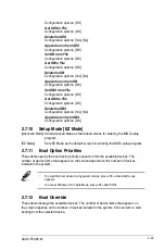
Anti Surge Support [Enabled]

This item allows you to enable or disable the Anti Surge function.

Configuration options: [Disabled] [Enabled]

Summary of Contents for F2A85-M

Page 1: ...Motherboard F2A85 M ...

Page 2: ...espective companies and are used only for identification or explanation and to the owners benefit without intent to infringe Offer to Provide Source Code of Certain Software This product contains copyrighted software that is licensed under the General Public License GPL under the Lesser General Public License Version LGPL and or other Free Open Source Software Licenses Such software in this produc...

Page 3: ... 8 1 4 1 Installing the APU 1 9 1 4 2 APU heatsink and fan assembly installation 1 10 1 5 System memory 1 12 1 5 1 Overview 1 12 1 5 2 Memory configurations 1 13 1 5 3 Installing a DIMM 1 20 1 5 4 Removing a DIMM 1 20 1 6 Expansion slots 1 21 1 6 1 Installing an expansion card 1 21 1 6 2 Configuring an expansion card 1 21 1 6 3 PCI slot 1 21 1 6 4 PCI Express x1 slot 1 21 1 6 5 PCI Express x16 slo...

Page 4: ... Auto 2 14 2 4 5 EPU Power Saving Mode Disabled 2 14 2 4 6 GPU Boost Auto 2 15 2 4 7 OC Tuner 2 15 2 4 8 DRAM Timing Control 2 15 2 4 9 CPU Voltage Offset Mode 2 15 2 4 10 DRAM Voltage Auto 2 16 2 4 11 SB 1 1V Voltage Auto 2 16 2 4 12 1 1VSB Voltage Auto 2 16 2 4 13 APU1 2V Voltage Auto 2 16 2 4 14 VDDA Voltage Auto 2 16 2 4 15 DIGI VRM 2 16 2 5 Advanced menu 2 18 2 5 1 CPU Configuration 2 18 2 5 ...

Page 5: ...st Logo Delay Time 3 sec 2 27 2 7 5 Wait for F1 If Error Enabled 2 27 2 7 6 Option ROM Messages Force BIOS 2 27 2 7 7 Next boot after AC Power Loss Normal Boot 2 28 2 7 8 CSM Parameters 2 28 2 7 9 Security Boot parameters 2 28 2 7 10 Setup Mode EZ Mode 2 29 2 7 11 Boot Option Priorities 2 29 2 7 12 Boot Override 2 29 2 8 Tools menu 2 30 2 8 1 ASUS EZ Flash 2 Utility 2 30 2 8 2 ASUS SPD Information...

Page 6: ...your area If you are not sure about the voltage of the electrical outlet you are using contact your local power company If the power supply is broken do not try to fix it by yourself Contact a qualified service technician or your retailer Operation safety Before installing the motherboard and adding devices on it carefully read all the manuals that came with the package Before using the product en...

Page 7: ...system settings through the BIOS Setup menus Detailed descriptions of the BIOS parameters are also provided Where to find more information Refer to the following sources for additional information and for product and software updates 1 ASUS websites The ASUS website provides updated information on ASUS hardware and software products Refer to the ASUS contact information 2 Optional documentation Yo...

Page 8: ...lete a task IMPORTANT Instructions that you MUST follow to complete a task NOTE Tips and additional information to help you complete a task Typography Bold text Indicates a menu or an item to select Italics Used to emphasize a word or a phrase Key Keys enclosed in the less than and greater than sign means that you must press the enclosed key Example Enter means that you must press the Enter or Ret...

Page 9: ... Graphics Integrated AMD Radeon HD 7000 Series Graphics in Trinity APU Multi VGA output support HDMI DVI D Sub port Supports HDMI with max resolution 1920x1080 60Hz Supports Dual link DVI with max resolution 2560x1600 60Hz Supports D Sub with max resolution 1920x1600 60Hz Supports Microsoft DirectX 11 Maximum shared memory of 2G Supports AMD Dual Graphics technology Refer to www amd com for the di...

Page 10: ...on ASUS Fan Xpert ASUS EZ DIY ASUS UEFI BIOS EZ Mode featuring friendly graphics user interface ASUS CrashFree BIOS 3 ASUS EZ Flash 2 ASUS My Logo 2 The ASUS Network iControl feature does not support Windows XP Vista operating systems ASUS Exclusive overclocking features Precision Tweaker 2 vCore Adjustable CPU voltage at 0 00625V increment vDDNB Adjustable CPU NB voltage at 0 00625V increment vDR...

Page 11: ...ctors gray 1 x CPU fan connector 4 pin 1 x Chassis fan connector 4 pin 1 x power Fan connector 3 pin 1 x Front panel audio connector 1 x S PDIF Out connector 1 x COM connector 1 x GPU Boost switch 1 x MemOK button 1 x TPM header 1 x System panel connector 20 8pin 1 x 24 pin EATX power connector 1 x 4 pin ATX 12V poweer connector BIOS features 64 Mb Flash ROM UEFI AMI BIOS PnP DMI 2 0 WfM 2 0 SM BI...

Page 12: ...ent models F2A85 M PCIEX16_1 PCIEX16_2 PCI1 PCIEX1_1 USB56 USB78 USB910 TPM PANEL SPDIF_OUT AAFP CPU_FAN PWR_FAN CHA_FAN Lithium Cell CMOS Power Super I O AUDIO ALC 887 VD2 RTL 8111F COM KBMS_USB34 64Mb BIOS SB_PWR CLRTC AMD A85X DDR3 DIMM_A1 64bit 240 pin module DDR3 DIMM_A2 64bit 240 pin module DDR3 DIMM_B1 64bit 240 pin module DDR3 DIMM_B2 64bit 240 pin module ESATA6G _USB3 _12 LAN _USB12 SATA6...

Page 13: ...your display configurations experiment with the advanced 3D settings and check the effects with a real time 3D rendered previews within AMD Catalyst Control Center Dual Channel DDR3 2400 O C 2250 O C 2200 O C 2133 O C 2000 O C 1866 1600 1333 1066MHz support The motherboard supports DDR3 memory that features data transfer rates of 2400 O C 2250 O C 2200 O C 2133 O C 2000 O C 1866 1600 1333 1066 MHz...

Page 14: ... delivery Boosetd by world renowned ASUS quality it creates an ideal computing platform for a diverse range of applications from gaming to multimedia or office work and heavy multitasking Engineered and tested to assure unmitigated performance ASUS A85X boards with DIGI VRM remain efficient and accurate for reliable application in every scenario DIGI VRM functions are also available in FM2 socket ...

Page 15: ...e adrenaline rush of real time overclocking without exiting or rebooting the OS It also provides you with the ASUS OC profiles for the best overclocking settings in different scenarios GPU Boost GPU Boost accelerates the integrated GPU for extreme graphics performance facilitates flexible frequency adjustments and easily delivers stable system level upgrades for every use Network iControl Network ...

Page 16: ... feature allows you to convert your favorite photo into a 256 color boot logo for a more colorful and vivid image on your screen ASUS CrashFree BIOS 3 ASUS CrashFree BIOS 3 is an auto recovery tool that allows you to restore a corrupted BIOS file using the bundled support DVD or USB flash disk that contains the latest BIOS file ASUS EZ Flash 2 ASUS EZ Flash 2 is a utility that allows you to update...

Page 17: ...bject or a metal object such as the power supply case to avoid damaging them due to static electricity Hold components by the edges to avoid touching the ICs on them Whenever you uninstall any component place it on a grounded antistatic pad or in the bag that came with the component Before you install or remove any component ensure that the ATX power supply is switched off or the power cord is det...

Page 18: ... physical injury and damage motherboard components 1 3 1 Placement direction When installing the motherboard ensure that you place it into the chassis in the correct orientation The edge with external ports goes to the rear part of the chassis as indicated in the image below 1 3 2 Screw holes Place eight screws into the holes indicated by circles to secure the motherboard to the chassis Do not ove...

Page 19: ...4Mb BIOS SB_PWR CLRTC 24 4cm 9 6in 24 4cm 9 6in AMD A85X DDR3 DIMM_A1 64bit 240 pin module DDR3 DIMM_A2 64bit 240 pin module DDR3 DIMM_B1 64bit 240 pin module DDR3 DIMM_B2 64bit 240 pin module ESATA6G _USB3 _12 LAN _USB12 SATA6G_6 SATA6G_5 SATA6G_7 SATA6G_4 SATA6G_3 SATA6G_2 SATA6G_1 SPDIFO _HDMI MemOK DRAM_LED DVI_VGA SOCKET FM2 EATXPWR USB3_34 GPU_LED GPU Boost ATX12V DIGI VRM 1 2 5 2 4 3 9 10 1...

Page 20: ...PANEL 1 31 12 TPM header 20 1 pin TPM 1 27 13 Clear RTC RAM 3 pin CLRTC 1 23 14 USB 3 0 connector 20 1 pin USB3_34 1 29 15 USB 2 0 connectors 10 1 pin USB56 USB78 USB910 1 29 16 Serial port connector 10 1 pin COM 1 28 17 Front panel audio connector 10 1 pin AAFP 1 26 18 Digital audio connector 4 1 pin SPDIF_OUT 1 26 1 4 Accelerated Processing Unit APU This motherboard comes with an FM2 socket desi...

Page 21: ...ASUS F2A85 M 1 9 1 4 1 Installing the APU 1 4 3 2 ...

Page 22: ...duction 1 2 5 3 4 1 4 2 APU heatsink and fan assembly installation Apply the Thermal Interface Material to the APU heatsink and APU before you install the heatsink and fan if necessary To install the APU heatsink and fan assembly ...

Page 23: ...ASUS F2A85 M 1 11 To uninstall the APU heatsink and fan assembly 5 3 1 4 2 ...

Page 24: ...hysical dimensions as a DDR2 DIMM but is notched differently to prevent installation on a DDR2 DIMM socket DDR3 modules are developed for better performance with less power consumption The figure illustrates the location of the DDR3 DIMM sockets Channel Sockets Channel A DIMM_A1 and DIMM_A2 Channel B DIMM_B1 and DIMM_B2 F2A85 M F2A85 M 240 pin DDR3 DIMM sockets DIMM_A1 DIMM_A2 DIMM_B1 DIMM_B2 ...

Page 25: ... do any of the following Install a maximum of 3GB system memory if you are using a 32 bit Windows OS Use a 64 bit Windows OS if you want to install 4GB or more memory on the motherboard This motherboard does not support DIMMs made up of 512Mb 64MB chips or less The maximum 64GB memory capacity can be supported with 16GB or above DIMMs ASUS will update the memory QVL once the DIMMs are available in...

Page 26: ...1 6V Kingston KHX2133C9AD3T1K2 4GX XMP 4GB 2 x 2GB DS 1 65V Kingston KHX2133C9AD3X2K2 4GX XMP 4GB 2 x 2GB DS 9 11 9 27 1 65V Kingston KHX2133C9AD3T1K4 8GX XMP 8GB 4 x 2GB DS 9 11 9 27 1 65V Kingston KHX2133C9AD3T1FK4 8GX XMP 8GB 4 x 2GB DS 1 65V PATRIOT PGD38G2133C11K XMP 16GB 4GB x 4 DS 11 11 11 30 1 65V Team TXD34096M2133HC9N L 4GB DS SEC 128 HCH9 K4B2G 0846D 9 11 11 28 1 65V Kingston KHX21C11T1...

Page 27: ...5V Corsair CMX4GX3M2A1600C9 XMP 4GB 2 x 2GB DS 9 9 9 24 1 65V Corsair CMX4GX3M2A1600C9 XMP 4GB 2 x 2GB DS 9 9 9 24 1 65V Corsair TR3X6G1600C8 G XMP 6GB 3 x 2GB DS 8 8 8 24 1 65V Corsair TR3X6G1600C8D G XMP 6GB 3 x 2GB DS 8 8 8 24 1 65V Corsair TR3X6G1600C9 G XMP 6GB 3 x 2GB DS 9 9 9 24 1 65V Corsair CMP8GX3M2A1600C9 XMP 8GB 2 x 4GB DS 9 9 9 24 1 65V Corsair CMZ8GX3M2A1600C7R XMP 8GB 2 x 4GB DS 7 8...

Page 28: ...SanMax SMD 4G68HP 16KZ 4GB DS HYNIX H5TQ2G83B FR PBC AMD AE32G1609U1 U 2GB SS 23EY4587M B6H11503M 9 9 9 24 1 5V AMD AE34G1609U2 U 4GB DS AMD 23EY4587M B6H11503M 9 9 9 24 1 5V ASint SLZ302G08 EGN1C 2GB SS Asint SLZ302G0 8 GN1C Asint SLZ3128M8 EGJ1D XMP 2GB DS Asint 3128M 8 GJ1D 9 9 9 24 1 6V Asint SLA302G08 EGG1C XMP 4GB DS Asint 302G0 8 GG1C Asint SLA302G08 EGJ1C XMP 4GB DS Asint 302G0 8 GJ1C ASin...

Page 29: ...GB SS 9 9 9 24 1 5V G SKILL F3 10666CL8D 4GBECO XMP 4GB 2 x 2GB DS 8 8 8 24 XMP 1 35V G SKILL F3 10666CL7D 8GBRH XMP 8GB 2 x 4GB DS 7 7 7 21 1 5V GEIL GV32GB1333C9DC 2GB 2 x 1GB DS 9 9 9 24 1 5V GEIL GG34GB1333C9DC 4GB 2 x 2GB DS GEIL GL1L128M88BA12N 9 9 9 24 1 3V low voltage GEIL GV34GB1333C9DC 4GB 2 x 2GB DS 9 9 9 24 1 5V GEIL GVP34GB1333C7DC 4GB 2 x 2GB DS 7 7 7 24 1 5V Hynix HMT112U6TFR8A H9 1...

Page 30: ... 9GF27D9KPT Transcend TS1GLK64V3H 8GB DS Micron IVD22D9PBC KINGSTEK KSTD3PC 10600 2GB SS MICRON PE911 125E AMD AE32G1339U1 U 2GB SS AMD 23EY4587MB3H11503M 9 9 9 24 1 5V AMD AE34G1339U2 U 4GB DS AMD 23EY4587MB3H11503M 9 9 9 24 1 5V ASint SLZ302G08 EDJ1C 2GB SS Asint SLZ302G08 DJ1C ASint SLA302G08 EDJ1C 4GB DS Asint SLA302G08 DJ1C ASint SLB304G08 EDJ1B 8GB DS Asint SLB304G08 DJ1B Elixir M2F2G64CB88B...

Page 31: ...ack slots as two pairs of Dual channel memory configuration Visit the ASUS website at www asus com for the latest QVL DDR3 1066 MHz capability Vendors Part No Size SS DS Chip Brand Chip NO Timing Voltage DIMM socket support Optional 1 DIMM 2 DIMMs 4 DIMMs Crucial CT12864BA1067 8FF 1GB SS Micron 9GF22D9KPT 7 Crucial CT25664BA1067 16FF 2GB DS Micron 9HF22D9KPT 7 ELPIDA EBJ10UE8EDF0 AE F 1GB SS ELPID...

Page 32: ... so that it fits in only one direction DO NOT force a DIMM into a socket in the wrong direction to avoid damaging the DIMM 3 Firmly insert the DIMM into the socket until the retaining clips snap back in place and the DIMM is properly seated Locked Retaining Clip 3 1 5 4 Removing a DIMM To remove a DIMM 1 Simultaneously press the retaining clips outward to unlock the DIMM 2 Remove the DIMM from the...

Page 33: ...rd is completely seated on the slot 5 Secure the card to the chassis with the screw you removed earlier 6 Replace the system cover 1 6 2 Configuring an expansion card After installing the expansion card configure it by adjusting the software settings 1 Turn on the system and change the necessary BIOS settings if any See Chapter 2 for information on BIOS setup 2 Assign an IRQ to the card 3 Install ...

Page 34: ...ent VGA configuration PCI Express operating mode PCIe x16_1 PCIe x16_2 Single VGA PCIe card x16 Recommended for single VGA card N A Dual VGA PCIe card x16 x4 1 6 5 PCI Express x16 slots This motherboard supports two PCI Express x16 graphics cards that comply with the PCI Express specifications IRQ assignments for this motherboard A B C D E F G H PCIe x16_1 shared PCIe x16_2 shared PCIe x1_1 shared...

Page 35: ... 2 3 Plug the power cord and turn ON the computer 4 Hold down the Del key during the boot process and enter BIOS setup to re enter data Except when clearing the RTC RAM never remove the cap on CLRTC jumper default position Removing the cap will cause system boot failure If the steps above do not help remove the onboard battery and move the jumper again to clear the CMOS RTC RAM data After clearing...

Page 36: ...ns LAN port LED indications LAN port Speed LED Activity Link LED 6 Center Subwoofer port orange This port connects the center subwoofer speakers 7 Rear Speaker Out port black This port connects the rear speakers in a 4 channel 6 channel or 8 channel audio configuration 8 Line In port light blue This port connects the tape CD DVD player or other audio sources 9 Line Out port lime This port connects...

Page 37: ...nd 2 These two 9 pin Universal Serial Bus USB ports connect to USB 3 0 2 0 devices DO NOT connect a keyboard mouse to any USB 3 0 port when installing Windows operating system Due to USB 3 0 controller limitation USB 3 0 devices can only be used under Windows OS environment and after the USB 3 0 driver installation USB 3 0 devices can only be used as data storage only We strongly recommend that yo...

Page 38: ...R PORT1 L PORT1 R PORT2 R SENSE_SEND PORT2 L HD audio compliant pin definition PIN 1 AGND NC NC NC MIC2 MICPWR Line out_R NC Line out_L Legacy AC 97 compliant definition 1 8 2 Internal connectors 1 Front panel audio connector 10 1 pin AAFP This connector is for a chassis mounted front panel audio I O module that supports either HD Audio or legacy AC 97 audio standard Connect one end of the front p...

Page 39: ... pin EATXPWR 4 pin ATX12V These connectors are for ATX power supply plugs The power supply plugs are designed to fit these connectors in only one orientation Find the proper orientation and push down firmly until the connectors completely fit F2A85 M F2A85 M ATX power connectors EATXPWR PIN 1 GND 5 Volts 5 Volts 5 Volts 5 Volts GND GND GND PSON GND 12 Volts 3 Volts 3 Volts 12 Volts 12 Volts 5V Sta...

Page 40: ...not place jumper caps on the fan connectors The CPU_FAN connector supports a CPU fan of maximum 2A 24 W fan power Only the 4 pin CPU fan and CHA FAN can support ASUS FanXpert feature F2A85 M F2A85 M Serial port COM connector PIN 1 COM DCD TXD GND RTS RI RXD DTR DSR CTS F2A85 M F2A85 M Fan connectors CPU_FAN PWR_FAN CPU FAN PWM CPU FAN IN CPU FAN PWR GND CHA_FAN GND CHA FAN PWR CHA FAN IN CHA FAN D...

Page 41: ...tely F2A85 M F2A85 M USB2 0 connectors USB 5V USB_P6 USB_P6 GND NC USB 5V USB_P5 USB_P5 GND USB56 PIN 1 USB 5V USB_P8 USB_P8 GND NC USB 5V USB_P7 USB_P7 GND USB78 PIN 1 USB 5V USB_P10 USB_P10 GND NC USB 5V USB_P9 USB_P9 GND USB910 PIN 1 8 USB 3 0 connector 20 1 pin USB3_34 This connector is for the additional USB 3 0 ports Connect the USB 3 0 bracket cable to this connector then install the USB 3 ...

Page 42: ...ration for details You must install Windows XP Service Pack 3 or later version before using Serial ATA hard disk drives The Serial ATA RAID feature is available only if you are using Windows XP SP3 or later version When using hot plug and NCQ set the type of the SATA connectors in the BIOS to AHCI See section 2 5 2 SATA Configuration for details SATA6G_1 SATA6G_2 GND RSATA_RXP1 RSATA_RXN1 GND RSAT...

Page 43: ...shes when data is read from or written to the HDD System warning speaker 4 pin SPEAKER This 4 pin connector is for the chassis mounted system warning speaker The speaker allows you to hear system beeps and warnings ATX power button soft off button 2 pin PWRSW This connector is for the system power button Pressing the power switch for more than four seconds while the system is ON turns the system O...

Page 44: ...irement the system automatically reboots when each timing set is tested If the installed DIMMs still fail to boot after the whole tuning process the DRAM_LED lights continuously Replace the DIMMs with ones recommended in the Memory QVL Qualified Vendors Lists in this user manual or on the ASUS website at www asus com If you turn off the computer and replace DIMMs during the tuning process the syst...

Page 45: ...t down the system and unplug the power cable before removing or plugging in any motherboard component The illustration below shows the location of the onboard LED 2 DRAM LED DRAM LED checks the DRAM in sequence during motherboard booting process If an error is found the LED next to the error device will continue lighting until the problem is solved This user friendly design provides an intuitional...

Page 46: ...1 34 Chapter 1 Product introduction 3 GPU Boost LED The GPU Boost LED lights when the GPU Boost switch is turned to Enable F2A85 M F2A85 M GPU Boost LED GPU_LED ...

Page 47: ...he drivers software applications and utilities that you can install to avail all motherboard features If Autorun is NOT enabled in your computer browse the contents of the Support DVD to locate the file ASSETUP EXE from the BIN folder Double click the ASSETUP EXE to run the DVD The following screen is for reference only The contents of the Support DVD are subject to change at any time without noti...

Page 48: ...1 36 Chapter 1 Product introduction ...

Page 49: ...that comes with the motherboard package Installing ASUS Update To install ASUS Update 1 Place the support DVD in the optical drive The Specials menu appears 2 Click the Utilities tab then click AI Suite II 3 Follow the onscreen instructions to complete the installation Quit all Windows applications before you update the BIOS using this utility Updating the BIOS To update the BIOS 1 From the Window...

Page 50: ...OS based utility Before you start using this utility download the latest BIOS file from the ASUS website at www asus com To update the BIOS using EZ Flash 2 1 Insert the USB flash disk that contains the latest BIOS file to the USB port 2 Enter the Advanced Mode of the BIOS setup program Go to the Tool menu to select ASUS EZ Flash 2 Utility and press Enter to enable it 3 Press Tab to switch to the ...

Page 51: ...ersion Download the latest BIOS file from the ASUS website at www asus com Recovering the BIOS To recover the BIOS 1 Turn on the system 2 Insert the support DVD to the optical drive or the USB flash drive that contains the BIOS file to the USB port 3 The utility automatically checks the devices for the BIOS file When found the utility reads the BIOS file and enters ASUS EZ Flash 2 utility automati...

Page 52: ...sus com and save them on the USB flash drive NTFS is not supported under DOS environment Do not save the BIOS file and BIOS Updater to a hard disk drive or USB flash drive in NTFS format 3 Turn off the computer and disconnect all SATA hard disk drives optional Booting the system in DOS environment 1 Insert the USB flash drive with the latest BIOS file and BIOS Updater to the USB port 2 Boot your c...

Page 53: ... to exit BIOS Updater Restart your computer DO NOT shut down or reset the system while updating the BIOS to prevent system boot failure For BIOS Updater version 1 30 or later the utility automatically exits to the DOS prompt after updating BIOS Ensure to load the BIOS default settings to ensure system compatibility and stability Select the Load Optimized Defaults item under the Exit menu Refer to ...

Page 54: ... keys to force reset from a running operating system can cause damage to your data or system We recommend to always shut down the system properly from the operating system The BIOS setup screens shown in this section are for reference purposes only and may not exactly match what you see on your screen Visit the ASUS website at www asus com to download the latest BIOS file for this motherboard Ensu...

Page 55: ... can be changed Refer to the Setup Mode item in section 2 7 Boot menu for details The boot device options vary depending on the devices you installed to the system The Boot Menu F8 button is available only when the boot device is installed to the system Exits the BIOS setup program without saving the changes saves the changes and resets the system or enters the Advanced Mode Selects the display la...

Page 56: ...f the screen has the following main items Main For changing the basic system configuration Ai Tweaker For changing the overclocking settings Advanced For changing the advanced system settings Monitor For displaying the system temperature power status and changing the fan settings Boot For changing the system boot configuration Tool For configuring options for special functions Exit For selecting t...

Page 57: ...n options for that item Scroll bar A scroll bar appears on the right side of a menu screen when there are items that do not fit on the screen Press the Up Down arrow keys or Page Up Page Down keys to display the other items on the screen Navigation keys At the bottom right corner of the menu screen are the navigation keys for the BIOS setup program Use the navigation keys to select items in the me...

Page 58: ...iguration options English Español Русский 2 3 2 System Date Day xx xx xxxx Allows you to set the system date 2 3 3 System Time xx xx xx Allows you to set the system time 2 3 4 Security The Security menu items allow you to change the system security settings If you have forgotten your BIOS password erase the CMOS Real Time Clock RTC RAM to clear the BIOS password See section 1 7 Jumpers for informa...

Page 59: ...hen prompted to create confirm the password After you clear the password the Administrator Password item on top of the screen shows Not Installed User Password If you have set a user password you must enter the user password for accessing the system The User Password item on top of the screen shows the default Not Installed After you set a password this item shows Installed To set a user password ...

Page 60: ...ou to configure overclocking related items Be cautious when changing the settings of the Ai Tweaker menu items Incorrect field values can cause the system to malfunction The configuration options for this section vary depending on the CPU and DIMM model you installed on the motherboard ...

Page 61: ...ASUS F2A85 M 2 13 Scroll down to display the following items Scroll down to display the following items ...

Page 62: ... 2 Memory Frequency Auto Allows you to set the memory operating frequency Configuration options DDR3 800MHz DDR3 1066MHz DDR3 1333MHz DDR3 1600MHz DDR3 1866MHz DDR3 2133MHz DDR3 2400MHz Selecting a very high memory frequency may cause the system to become unstable If this happens revert to the default setting 2 4 3 APU Multiplier Auto Allows you to set the multiplier between the APU Core Clock and...

Page 63: ...nd press Enter Changing the values in this menu may cause the system to become unstable If this happens revert to the default settings 2 4 9 CPU Voltage Offset Mode Offset Mode To offset the voltage by a positive or negative value CPU Offset Mode Sign To offset the voltage by a positive value To offset the voltage by a negative value CPU Offset Voltage Auto Allows you to set the CPU Offset voltage...

Page 64: ... the risk levels of high voltage settings The system may need better cooling system to work stably under high voltage settings 2 4 15 DIGI VRM CPU Load Line Calibration Auto Load line Calibration is defined by AMD VRM specifications and affects CPU voltage The CPU working voltage will decrease proportionally to CPU loading Higher load line calibration would get higher voltage and better overclocki...

Page 65: ...ding on the CPU loading Optimized Loads the ASUS optimized phase tuning profile Extreme Proceeds the full phase mode Manual Adjustment Adjustment Allows manual adjustment DO NOT remove the thermal module when switching to Extreme and Manual Mode The thermal conditions should be monitored CPU Voltage Frequency 300Khz Allows you to set the CPU Voltage Frequency The values range from 200Khz to 350Khz...

Page 66: ...tion The items in this menu show the CPU related information that the BIOS automatically detects The items shown in submenu may be different due to the CPU you installed AMD PowerNow function Enabled Enables or disables the AMD PowerNow function Configuration options Enabled Disabled NX Mode Enabled Enables or disables the No execute page protection function Configuration options Enabled Disabled ...

Page 67: ...ves to use the AHCI Advanced Host Controller Interface The AHCI allows the onboard storage driver to enable advanced Serial ATA features that increases storage performance on random workloads by allowing the drive to internally optimize the order of commands SATA Port 5 6 7 ESATA AHCI or RAID This item only appears when the previous item is set to AHCI or RAID If Port 5 6 7 ESATA are configured as...

Page 68: ...sabled Disables the function EHCI Hand off Disabled Enabled Enables the support for operating systems without an EHCI hand off feature Disabled Disables the function 2 5 4 NB Configuration IGFX Multi Monitor Disabled Enables or disables the Internal Graphics Device Multi Monitor support for add on VGA devices And the memory size of Internal Graphics Device will keep memory reserved Configuration o...

Page 69: ...ort Configuration The sub items in this menu allow you to set the serial port configuration Serial Port Enabled Allows you to enable or disable the serial port COM Configuration options Enabled Disabled Change Settings Auto This item appears only when you set the previous item to Enabled and allows you to select the Serial Port base address Configuration options Auto IO 3F8h IRQ 4 IO 2F8h IRQ 3 IO...

Page 70: ...vent Enabled Enables Ring to generate a wake event Power On By RTC Disabled Disabled Disables RTC to generate a wake event Enabled When set to Enabled the items RTC Alarm Date Days and Hour Minute Second will become user configurable with set values 2 5 7 Network Stack Network Stack Disable Link This item allows user to disable or enable the UEFI network stack Configuration options Disable Link En...

Page 71: ...e CPU and motherboard temperatures Select Ignore if you do not wish to display the detected temperatures 2 6 2 CPU PWR Chassis Fan Speed xxxx RPM or Ignore N A The onboard hardware monitor automatically detects and displays the CPU and chassis fan speeds in rotations per minute RPM If the fan is not connected to the motherboard the field shows N A Select Ignore if you do not wish to display the de...

Page 72: ...g four items appear only when you set CPU Fan Profile to Manual CPU Upper Temperature 70 Use the and keys to adjust the upper limit of the CPU temperature The values range from 20ºC to 90ºC CPU Fan Max Duty Cycle 100 Use the and keys to adjust the maximum CPU fan duty cycle The values range from 40 to 100 When the CPU temperature reaches the upper limit the CPU fan will operate at the maximum duty...

Page 73: ...from 20ºC to 90ºC CHA_FAN Fan Max Duty Cycle 100 Use the and keys to adjust the maximum chassis fan duty cycle The values range from 40 to 100 When the chassis temperature reaches the upper limit the chassis fan will operate at the maximum duty cycle CHA_FAN Lower Temperature 20 Displays the lower limit of the chassis temperature CHA_FAN Fan Min Duty Cycle 40 Use the and keys to adjust the minimum...

Page 74: ... menu The Boot menu items allow you to change the system boot options 2 7 1 Bootup NumLock State On On Sets the power on state of the NumLock to On Off Sets the power on state of the NumLock to Off Scroll down to display the following items ...

Page 75: ...nitial All the USB devices will be available during POST and in OS Partial Initial Specific USB device port will be available before entering OS PS2 Devices Support Enabled Disabled Disables the PS2 devices support during POST Enabled Enables the PS 2 devices support during POST Network Stack Driver Support Disabled Disabled Disables network stack driver support during POST Enabled Enables network...

Page 76: ...uration option Both Legacy OpROM first Both UEFI first Legacy OpROM first UEFI driver first Ignore Boot from PCIe PCI Expansion Devices Legacy OpR Configuration option Legacy OpROM first UEFI driver first 2 7 9 Security Boot parameters This option allows you to configure the Security Boot parameters OS Type Other Lega Configuration option Windows 8 UEFI Other Legacy UEFI Secure Boot Mode Standard ...

Page 77: ...vanced Mode Sets Advanced Mode as the default screen for entering the BIOS setup program EZ Mode Sets EZ Mode as the default screen for entering the BIOS setup program 2 7 11 Boot Option Priorities These items specify the boot device priority sequence from the available devices The number of device items that appears on the screen depends on the number of devices installed in the system To select ...

Page 78: ...M B1 DIMM B2 2 8 3 ASUS O C Profile This item allows you to store or load multiple BIOS settings The Setup Profile Status items show Not Installed if no profile is created Save to Profile Allows you to save the current BIOS settings to the BIOS Flash and create a profile Key in a profile number from one to eight press Enter and then select Yes Load from Profile Allows you to load the previous BIOS...

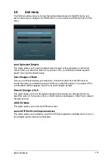
Page 79: ...nished making your selections choose this option from the Exit menu to ensure the values you selected are saved When you select this option or if you press F10 a confirmation window appears Select Yes to save changes and exit Discard Changes Exit This option allows you to exit the Setup program without saving your changes When you select this option or if you press Esc a confirmation window appear...

Page 80: ...2 32 Chapter 2 Getting started ...

Page 81: ... harmful interference to radio communications However there is no guarantee that interference will not occur in a particular installation If this equipment does cause harmful interference to radio or television reception which can be determined by turning the equipment off and on the user is encouraged to try to correct the interference by one or more of the following measures Reorient or relocate...

Page 82: ...appareil numérique de la Classe B respecte toutes les exigences du Règlement sur le matériel brouilleur du Canada Cet appareil est conforme aux normes CNR exemptes de licence d Industrie Canada Le fonctionnement est soumis aux deux conditions suivantes 1 cet appareil ne doit pas provoquer d interférences et 2 cet appareil doit accepter toute interférence y compris celles susceptibles de provoquer ...

Page 83: ...ot be placed in municipal waste Check local regulations for disposal of electronic products DO NOT throw the mercury containing button cell battery in municipal waste This symbol of the crossed out wheeled bin indicates that the battery should not be placed in municipal waste ASUS Recycling Takeback Services ASUS recycling and takeback programs come from our commitment to the highest standards for...

Page 84: ...Way Fremont CA 94539 USA Telephone 1 812 282 3777 Fax 1 510 608 4555 Web site usa asus com Technical Support Telephone 1 812 282 2787 Support fax 1 812 284 0883 Online support support asus com ASUS COMPUTER GmbH Germany and Austria Address Harkort Str 21 23 D 40880 Ratingen Germany Fax 49 2102 959911 Web site www asus de Online contact www asus de sales Technical Support Telephone 49 1805 010923 S...

Page 85: ...erboard Model name F2A85 M conform with the essential requirements of the following directives 2004 108 EC EMC Directive EN 55022 2010 EN 61000 3 2 2006 A1 2009 A2 2009 EN 55013 2001 A1 2003 A2 2006 EN 55024 2010 EN 61000 3 3 2008 EN 55020 2007 A11 2011 1999 5 EC R TTE Directive EN 300 328 V1 7 1 2006 10 EN 300 440 1 V1 6 1 2010 08 EN 300 440 2 V1 4 1 2010 08 EN 301 511 V9 0 2 2003 03 EN 301 908 1...

Page 86: ...A 6 Appendices ...
Reviews: