background image

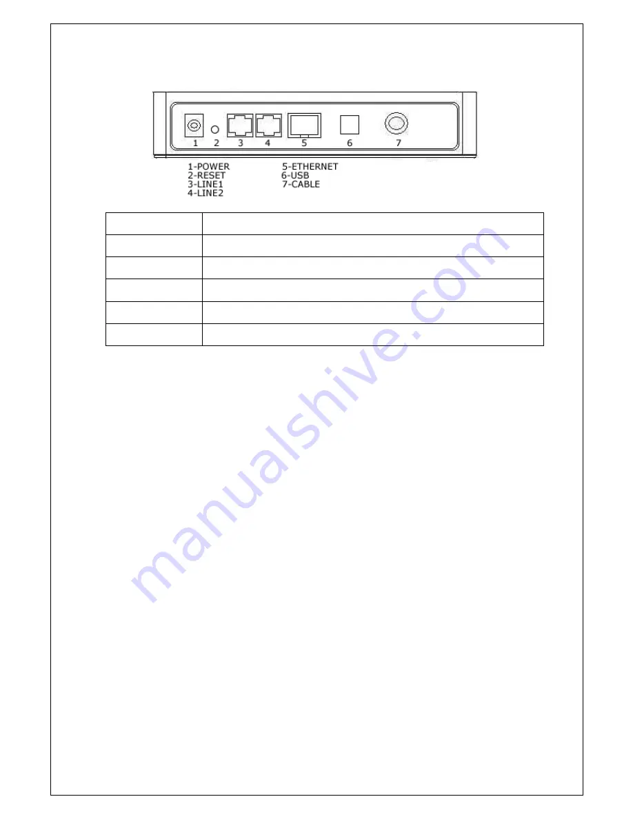
The back panel components of the eMTA is described in the following illustration— 


RF Interface 

F-Type Female 75ohm Connector 


WAN and LAN 

One 10/100Mbps fast Ethernet Switch. 


USB 

One USB 1.1 function port for connectivity to a PC 


Phone Line 

RJ-11 Telephone Socket x 2 


Reset Button 

Push to reset eMTA  


Power  

12V, 1A 


V.1

 eMTA 

Cable Modem User Manual 


Summary of Contents for eMTA

Page 1: ...eMTA VoIP over Cable Modem User Manual Version 1 0 ...

Page 2: ...aners or magnetic static cleaning devices Do not obstruct the ventilation openings of this equipment to prevent overheating Plug this equipment into a surge protector to reduce the risk of damage from power surges and lightning strikes Do not open the cover of this equipment Contact your cable service provider for servicing questions Operate this equipment only from an electrical outlet with the c...

Page 3: ...ECEIVE Green ON Downstream is OK SEND Green ON Upstream is OK ONLINE Green ON eMTA is operational ON Ethernet port is being connected ETHERNET Green Blinking Data is transporting via Ethernet ON USB port is being connected USB Green Blinking Data is transporting via USB port LINE1 Green ON Phone port 1 is being used LINE2 Green ON Phone port 2 is being used STANDBY Green ON Ethernet USB access dis...

Page 4: ...lustration RF Interface F Type Female 75ohm Connector WAN and LAN One 10 100Mbps fast Ethernet Switch USB One USB 1 1 function port for connectivity to a PC Phone Line RJ 11 Telephone Socket x 2 Reset Button Push to reset eMTA Power 12V 1A V 1 eMTA Cable Modem User Manual ...

Page 5: ...e mail access the web and receive other Internet services NOTE Place the eMTA in a proper location with adequate airflow Your PC and eMTA should be placed near your cable input with plenty of space for the cable eMTA Installation System Requirements The following lists the minimum hardware and software system requirements necessary for connecting your eMTA to your PC Minimum System Requirements fo...

Page 6: ...AC power source 4 Plug in your PC and turn on the power 5 Connect the telephone port to your home telephone jack or directly plug a telephone into the telephone port 6 Connect the active RF coaxial cable to the CABLE connector Note To add a TV a DHCT or set top box or a VCR use an optional cable signal splitter 7 Once connected the eMTA will begin an automatic search which may take up to 5 minutes...

Page 7: ...ances Telephone Requirements The following lists the minimum hardware and software system requirements necessary for using your eMTA for telephone service Number of Telephone Devices The maximum number of telephone devices e g telephones fax machines and analog modems is limited by the total Ringing Load of the telephone devices that are connected Each telephone port on the eMTA can support up to ...

Page 8: ...er adapter cord into the power connector on the back of the eMTA and then plug the power adapter into an AC power source 3 Connect the active RF coaxial cable to the CABLE connector on the back of the eMTA 4 Once connected the eMTA begins an automatic search which may take 5 minutes to locate and sign on to the network that provides the telephone service 5 Verify that there is a dial tone and inco...

Page 9: ...al number and MAC address If you are using a cable splitter to connect the eMTA to other devices remove the splitter and reconnect the cable of the eMTA directly to the cable input If this works then the cable splitter may need to be replaced Internet Service If an Ethernet connection cannot be registered Verify that your computer has a 10 100 BaseT Ethernet card and the Ethernet driver software i...

Reviews: