background image

ASUS Desktop PC

71

ENGLISH

ENGLISH

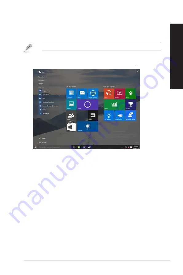
Start screen

The Start screen , which appears together with the Start menu, helps organize all the apps you need 

in just one place. The apps on the Start screen are displayed on tiled-format for easy access.

Some apps require signing in to your Microsoft account before they are fully launched.

Click to restore the 

Start screen

Moving apps on the Start screen

You can move apps from the Start screen simply through dragging and dropping the app to your 

preferred location.

Unpinning apps from the Start screen

To unpin an app from the Start screen, right-click on the app to activate its settings bar then click 

Unpin from Start

.

Summary of Contents for D640MA

Page 1: ...ASUS Desktop PC User Guide SD MMC MS Smart Card SD MMC MS Smart Card SD MMC MS Smart Card D640MA D640MB M640MB W640MB S640MB D640SA M640SA W640SA ...

Page 2: ...RTICULAR PURPOSE IN NO EVENT SHALL ASUS ITS DIRECTORS OFFICERS EMPLOYEES OR AGENTS BE LIABLE FOR ANY INDIRECT SPECIAL INCIDENTAL OR CONSEQUENTIAL DAMAGES INCLUDING DAMAGES FOR LOSS OF PROFITS LOSS OF BUSINESS LOSS OF USE OR DATA INTERRUPTION OF BUSINESS AND THE LIKE EVEN IF ASUS HAS BEEN ADVISED OF THE POSSIBILITY OF SUCH DAMAGES ARISING FROM ANY DEFECT OR ERROR IN THIS MANUAL OR PRODUCT SPECIFICA...

Page 3: ...to the external audio output 35 Chapter 3 Using your computer Proper posture when using your Desktop PC 37 Using the memory card reader Optional 38 Using the optical drive on selected models only 39 Configuring the USB ports using the BIOS 41 Configuring the HDD security setting using the BIOS 42 Chapter 4 Connecting to the Internet Wired connection 43 Chapter 5 Using ASUS Business Manager ASUS Bu...

Page 4: ...interference in a residential installation This equipment generates uses and can radiate radio frequency energy and if not installed and used in accordance with manufacturer s instructions may cause harmful interference to radio communications However there is no guarantee that interference will not occur in a particular installation If this equipment does cause harmful interference to radio or te...

Page 5: ...canaux CAN ICES 3 B NMB 3 B IC Canadian Compliance Statement Complies with the Canadian ICES 003 Class B specifications This device complies with RSS 210 of Industry Canada This Class B device meets all the requirements of the Canadian interference causing equipment regulations This device complies with Industry Canada license exempt RSS standard s Operation is subject to the following two conditi...

Page 6: ...Management Rules 2016 and prohibits use of lead mercury hexavalent chromium polybrominated biphenyls PBBs and polybrominated diphenyl ethers PBDEs in concentrations exceeding 0 1 by weight in homogenous materials and 0 01 by weight in homogenous materials for cadmium except for the exemptions listed in Schedule II of the Rule Canadian Department of Communications Statement This digital apparatus d...

Page 7: ...ted output power of the Wi Fi technology is below the FCC radio frequency exposure limits Nevertheless it is advised to use the wireless equipment in such a manner that the potential for human contact during normal operation is minimized FCC BluetoothWireless Compliance The antenna used with this transmitter must not be colocated or operated in conjunction with any other antenna or transmitter sub...

Page 8: ... attempt to disassemble or repair the optical drive by yourself For your safety contact a professional technician for assistance Service warning label WARNING INVISIBLE LASER RADIATION WHEN OPEN DO NOT STARE INTO BEAM OR VIEW DIRECTLY WITH OPTICAL INSTRUMENTS CDRH Regulations The Center for Devices and Radiological Health CDRH of the U S Food and Drug Administration implemented regulations for las...

Page 9: ...wer cable from the electrical outlet before relocating the system Seek professional assistance before using an adapter or extension cord These devices could interrupt the grounding circuit Ensure that your power supply is set to the correct voltage in your area If you are not sure about the voltage of the electrical outlet you are using contact your local power company If the power supply is broke...

Page 10: ...nd more information Refer to the following sources for additional information and for product and software updates ASUS websites The ASUS website provides updated information on ASUS hardware and software products Refer to the ASUS website www asus com ASUS LocalTechnical Support Visit ASUS website at http support asus com contact for the contact information of local Technical Support Engineer Haz...

Page 11: ...trated items above are for reference only Actual product specifications may vary with different models SD MMC MS Smart Card ASUS Desktop PC Keyboard x1 Mouse x1 Power cord x1 Support DVD x1 Recovery DVD x1 Optional Installation Guide ASUS mouse pad x 1 Optional Installation Guide x1 Warranty card x1 ...

Page 12: ...12 ...

Page 13: ...compromised reliability and user centric utilities All these values are encapsulated in a stunningly futuristic and stylish system casing Read the ASUS Warranty Card before setting up your ASUS Desktop PC The Desktop PC does not support Windows 7 operating system ASUS is not responsible for any loss or damage incurred by installing Window 7 Be careful when handling the desktop PC to prevent the ri...

Page 14: ... 2 0 ports These Universal Serial Bus 2 0 USB 2 0 ports connect to USB 2 0 devices such as a mouse printer scanner camera PDA and others 9 3 5 inch drive bay This 3 5 inch drive bay is for 3 5 inch hard disk drives memory card readers D640MA Front panel SD MMC MS Smart Card USB 3 1 Gen 1 orType C port for data transfer only USB 3 1 Gen 1 port The M 2 socket shares bandwidth with SATA6G_1 and SATA6...

Page 15: ...rt This port is for a High Definition Multimedia Interface HDMI connector and is HDCP compliant allowing playback of HD DVD Blu ray and other protected content 5 USB 3 1 Gen 2 ports These 9 pin Universal Serial Bus USB ports are for USB 3 1 Gen 2 devices We strongly recommend that you connect USB 3 1 Gen 2 devices to USB 3 1 Gen 2 ports for faster and better performance for your USB 3 1 Gen 2 devi...

Page 16: ... PC to be secured using Kensington compatible PC security cables 14 LAN RJ 45 port This port allows Gigabit connection to a Local Area Network LAN through a network hub 7 USB 2 0 ports These Universal Serial Bus 2 0 USB 2 0 ports connect to USB 2 0 devices such as a mouse printer scanner camera PDA and others 8 Microphone port pink This port connects to a microphone 9 Line Out port lime This port ...

Page 17: ... 5 inch hard disk drives memory card readers 5 Power button Press this button to turn on your computer 6 USB 3 1 Gen 1 orType C port This port connects to USB 3 1 Gen 1 or Type C devices for data transfer only 7 USB 3 1 Gen 1 port This port connects to USB 3 1 Gen 1 devices such as a mouse printer scanner camera PDA and others 8 USB 2 0 ports These Universal Serial Bus 2 0 USB 2 0 ports connect to...

Page 18: ...environment will seriously damage the system 80 Plus power supplies do not provide a voltage switch 2 Power connector Plug the power cord to this connector RATING 115 230Vac 50 60Hz 6 3A or 220 230Vac 50Hz 3A or 230Vac 50Hz 3A or 100 120Vac 50 60Hz 8A 3 PS 2 mouse port green This port is for a PS 2 mouse 4 PS 2 keyboard port purple This port is for a PS 2 keyboard 5 HDMI port This port is for a Hi...

Page 19: ...4 1 5 1 or 7 1 channel configuration Audio 2 1 4 1 5 1 or 7 1 channel configuration Port Headset 2 1 channel 4 1 channel 5 1 channel 7 1 channel Light Blue Rear panel Line In Rear Speaker Out Rear Speaker Out Rear Speaker Out Lime Rear panel Line Out Front Speaker Out Front Speaker Out Front Speaker Out Pink Rear panel Mic In Mic In Bass Center Bass Center Lime Front panel Side Speaker Out 12 Kens...

Page 20: ...tion DO NOT block the air vents on the chassis Always provide proper ventilation for your computer 20 VGA port This port is for VGA compatible devices such as a VGA monitor 18 LAN RJ 45 port This port allows Gigabit connection to a Local Area Network LAN through a network hub LAN port LED indications D640SA M640SA W640SA Front Panel SD MMC MS Smart Card USB 3 1 Gen 1 orType C port for data transfe...

Page 21: ...s port connects to USB 3 1 Gen 1 or Type C devices for data transfer only 8 USB 2 0 ports These Universal Serial Bus 2 0 USB 2 0 ports connect to USB 2 0 devices such as a mouse printer scanner camera PDA and others 9 Headphone port lime This port connects to a headphone or speaker 10 Microphone port pink This port connects to a microphone The M 2 socket shares bandwidth with SATA6G_1 and SATA6G_2...

Page 22: ... Gen 2 devices to USB 3 1 Gen 2 ports for faster and better performance for your USB 3 1 Gen 2 devices 5 DisplayPort These ports are for DisplayPort compatible devices 6 USB 2 0 ports These Universal Serial Bus 2 0 USB 2 0 ports connect to USB 2 0 devices such as a mouse printer scanner camera PDA and others 7 Microphone port pink This port connects to a microphone 8 Line Out port lime This port c...

Page 23: ...te system input voltage according to the voltage supply in your area If the voltage supply in your area is 100 127V set the switch to 115V If the voltage supply in your area is 200 240V set the switch to 230V Setting the switch to 115V in a 230V environment or 230V in a 115V environment will seriously damage the system 80 Plus power supplies do not provide a voltage switch 13 Air vents These vents...

Page 24: ...Graphics Card 2 Plug the monitor to a power source The display output ports on the ASUS Graphics Card may vary with different models 16 Pad lock slot This pad lock slot allows your PC to be secured using a standard pad lock 17 Kensington lock slot The Kensington lock slot allows the PC to be secured using Kensington compatible PC security cables 18 Parallel port optional This 25 pin port connects ...

Page 25: ...t on the rear panel of your computer 2 Plug the monitor to a power source If your computer comes with an ASUS Graphics Card the graphics card is set as the primary display device in the BIOS Hence connect your monitor to a display output port on the graphics card To connect multiple external monitors to your computer refer to Connecting multiple external display in Chapter 2 of this guide for deta...

Page 26: ... a USB mouse to the USB ports on the rear panel of your computer Connecting the power cord Connect one end of the power cord to the power connector on the rear panel of your computer and the other end to a power source D640MA D640MA 26 Chapter 1 Getting started ENGLISH ...

Page 27: ... multiple displays 1 Turn off your computer 2 Connect the two monitors to your computer and connect the power cords to the monitors Refer to Setting up your computer section in Chapter 1 for details on how to connect a monitor to your computer 3 Turn on your computer 4 From the Start menu click Settings System Display 5 Configure the settings for your displays For some graphic cards only the monit...

Page 28: ...g your computer ON To turn your computer ON 1 Turn your monitor ON 2 Press the power button on your computer 3 Wait until the operating system loads automatically SD MMC MS Smart Card Power button Power button SD MMC MS Smart Card D640MA D640SA M640SA W640SA D640MB M640MB W640MB S640MB Power button 28 Chapter 1 Getting started ENGLISH ...

Page 29: ... computer You can enable or disable the front and rear USB 2 0 USB 3 1 Gen 1 and USB 3 1 Gen 2 ports individually from the BIOS Setup Refer to the Configuring the USB ports using the BIOS section in Chapter 3 of this user manual for details SD MMC M S Smart Card ASUS Desktop PC 29 ENGLISH Chapter 2 Connecting devices to your computer Front panel SD MMC MS Smart Card SD MMC MS Smart Card SD MMC MS ...

Page 30: ...30 Chapter 2 Connecting devices to your computer ENGLISH Rear panel D640MA D640SA M640SA W640SA D640MB M640MB W640MB S640MB ...

Page 31: ...p PC comes with an internal speaker the audio output will be from the internal speaker When you connect an external audio device such as earphone or speaker you need to enable the audio device output For details refer to the section Changing to the external audio output When you disconnect the audio device you need to manually change the audio output to the internal speaker from the Control Panel ...

Page 32: ...SD MMC MS Smart Card SD MMC MS Smart Card SD MMC MS Smart Card Smart Card D640MB M640MB W640MB S640MB D640SA M640SA W640SA 32 Chapter 2 Connecting devices to your computer ENGLISH ...

Page 33: ...Connecting 2 1 channel Speakers LINE OUT Connecting 4 1 channel Speakers LINE OUT ASUS Desktop PC 33 ENGLISH ...

Page 34: ...Connecting 5 1 channel Speakers LINE OUT Connecting 7 1 channel Speakers LINE OUT SD MMC MS Smart Card 34 Chapter 2 Connecting devices to your computer ENGLISH ...

Page 35: ...output 1 Connect an external audio device such as earphone or speaker to the rear Line Out port The Audio Manager screen automatically pops up For the location of the rear Line Out port refer to the section Getting to know your computer 2 Tick Front Speaker Out then click OK 3 Tick Line In then click OK The audio output will now be from the external audio device The Audio Manager screenshots above...

Page 36: ...36 Chapter 2 Connecting devices to your computer ENGLISH ...

Page 37: ...chair to make sure that your knees are slightly higher than your hips to relax the backs of your thighs If necessary use a footrest to raise the level of your knees Adjust the back of your chair so that the base of your spine is firmly supported and angled slightly backward Sit upright with your knees elbows and hips at an approximately 90º angle when you are at the PC Place the monitor directly i...

Page 38: ...endently Place only one memory card in a slot at one time 2 Select a program from the AutoPlay window to access your files If AutoPlay is NOT enabled in your computer click File Explorer from the Start menu and then double click the memory card icon to access the data on it Each card slot has its own drive icon which is displayed on the File Explorer screen 3 When finished right click the memory c...

Page 39: ...Using the optical drive on selected models only SD MMC MS Smart Card 1 SD MMC MS Smart Card 3 2 SD MMC MS Smart Card SD MMC MS Smart Card D640MA D640SA M640SA W640SA 3 2 1 ASUS Desktop PC 39 ENGLISH ...

Page 40: ...a program from the AutoPlay window to access your files Removing an optical disc To remove an optical disc 1 While the system is on do either of the following to eject the tray Press the eject button below the drive bay cover From the Start menu click File Explorer right click the CD DVD drive icon and click Eject 2 Remove the disc from the disc tray If AutoPlay is NOT enabled in your computer to ...

Page 41: ... USB 3 1 Gen 2 ports 1 Press Delete to enter the BIOS Setup at startup 2 From the BIOS Setup screen click Advanced USB Configuration USB Single Port Control 3 Select the USB port that you want to enable or disable 4 Press Enter to enable or disable the selected USB port 5 Click Exit and select Save Changes Reset to save the changes made Refer to Chapter 1 for the location of the USB ports ASUS Des...

Page 42: ... Take note of this password which you would need to access the HDD To change the password for your HDD from the BIOS Setup 1 Follow steps 1 and 2 of the previous section to open the HDD Password screen 2 Select the Set User Password item and press Enter 3 From the Enter Current Password box key in the current password then press Enter 4 From the Create New Password box key in a new password then p...

Page 43: ...our computer to a DSL cable modem or a local area network LAN 2 Connect one end of an RJ 45 cable to the LAN RJ 45 port on the rear panel of your computer and the other end to a DSL cable modem Refer to the documentation that came with your DSL cable modem Modem RJ 45 cable D640MA ASUS Desktop PC 43 ENGLISH Chapter 4 Connecting to the Internet ...

Page 44: ...tor for details or assistance in setting up your Internet connection For more details refer to the sections Configuring a dynamic IP PPPoE network connection or Configuring a static IP network connection D640SA M640SA W640SA D640MB M640MB W640MB S640MB Modem RJ 45 cable Modem RJ 45 cable 44 Chapter 4 Connecting to the Internet ENGLISH ...

Page 45: ...N To connect via a LAN 1 Connect one end of an RJ 45 cable to the LAN RJ 45 port on the rear panel of your computer and the other end to your LAN RJ 45 cable LAN D640MA LAN RJ 45 cable D640MB M640MB W640MB S640MB ASUS Desktop PC 45 ENGLISH ...

Page 46: ...k administrator for details or assistance in setting up your Internet connection For more details refer to the sections Configuring a dynamic IP PPPoE network connection or Configuring a static IP network connection LAN RJ 45 cable D640SA M640SA W640SA 46 Chapter 4 Connecting to the Internet ENGLISH ...

Page 47: ...Center b From the Start menu click Settings Network Internet Ethernet Network and Sharing Center 2 From the Open Network and Sharing Center screen click Change Adapter settings 3 Right click on your LAN and select Properties 4 Click Internet ProtocolVersion 4 TCP IPv4 and click Properties 5 Click Obtain an IP address automatically and click OK Continue to the next steps if you are using PPPoE conn...

Page 48: ...48 Chapter 4 Connecting to the Internet ENGLISH ...

Page 49: ... your ASUS support DVD into your optical drive 2 On the support CD window click Utilities ASUS Business Manager 3 On the ASUS Manager setup screen select the applications you want to install 4 Click Install 5 The system will prompt you to reboot your system once installation is complete ASUS Desktop PC 49 ENGLISH Chapter 5 Using ASUS Business Manager ...

Page 50: ...Menu by clicking Start ASUS ASUS Manager IconView and ListView ASUS Manager has an Icon View and List View Click the ListView icon to display a list of tools available for your system IconView ListView ListView 50 Chapter 5 Using ASUS Business Manager ENGLISH ...

Page 51: ...screen displays hardware and software details about your computer Update Click Update on the main ASUS Manager screen to download and install hardware drivers the latest BIOS and updated ASUS applications ASUS Desktop PC 51 ENGLISH ...

Page 52: ...C Cleanup provides options to remove temporary and unnecessary files from your computer to free up hard drive space ASUS Secure Delete ASUS Secure Delete keeps your files secure by making deleted files completely irrecoverable using a simple drag and drop interface 52 Chapter 5 Using ASUS Business Manager ENGLISH ...

Page 53: ... then click Right click the file then select ASUS Secure Delete To use ASUS Secure Delete 3 Tick Delete the files listed in the recycle bin if you want to permanently delete all the files in the recycle bin 4 Click Clear and then click OK on the confirmation message to permanently delete all the files listed in the deletion box and the recycle bin if selected in step 3 ASUS Desktop PC 53 ENGLISH ...

Page 54: ...enance tasks such as system restoration adjusting startup settings and repairing Windows with a recovery disk USB Lock The USB Lock feature secures your USB ports card reader and optical drive from unwanted access by setting up a password 54 Chapter 5 Using ASUS Business Manager ENGLISH ...

Page 55: ...ger you can specity time settings for system hibernation sleep display and hard drive activity Tool Click Tool on the main ASUS Manager screen to access the Support screen Ai Booting or MyLogo Support Support lists links to ASUS support web sites and contact information ASUS Desktop PC 55 ENGLISH ...

Page 56: ...Select a device and click the left right buttons to modify the boot sequence MyLogo ASUS MyLogo allows you to customize the boot logo The boot logo is the image that appears on screen during the Power On Self Tests POST 56 Chapter 5 Using ASUS Business Manager ENGLISH ...

Page 57: ...IOS boot logo only Before selecting the first option download the BIOS file to your computer using ASUS Update 2 Click Browse to locate the picture file that you want to use as the boot logo and the downloaded BIOS if required and then click Run 3 Follow the onscreen instructions to complete the process ASUS Desktop PC 57 ENGLISH ...

Page 58: ...ctions to complete the setup Configuring a static IP network connection To configure a static IP network connection 1 Repeat steps 1 to 4 of the previous section 2 Click Use the following IP address 3 Enter the IP address Subnet mask and Gateway from your service provider 4 If needed enter the preferred DNS Server address and alternative address 5 When done click OK 58 Chapter 5 Using ASUS Busines...

Page 59: ... not responding 1 Simultaneously press Alt Ctrl Delete keys on the keyboard then click Task Manager 2 Select the program that is not responding then click EndTask If the keyboard is not responding press and hold the Power button on the top of your chassis until the computer shuts down Then press the Power button to turn it on I cannot connect to a wireless network using the ASUSWLAN Card on select...

Page 60: ...or is plugged to a power source properly Refer to the documentation that came with your monitor for more troubleshooting information When using multiple monitors only one monitor has display Ensure that the both monitors are powered on During POST only the monitor connected to the VGA port has display The dual display function works only under Windows When a graphics card is installed on your comp...

Page 61: ...uce no sound Ensure that you connect your speakers to the Line out port lime on the front panel or the rear panel Check if your speak is connected to an electrical source and turned on Adjust your speakers volume Ensure that your computer s system sounds are not Muted If it is muted the volume icon is displayed as To enable the system sounds click from the Windows notification area then click If i...

Page 62: ...nsure that the power cord is properly connected Use other compatible power cord PSU Power supply unit problems Contact the ASUS Service Center about installing another PSU on your computer Display Problem Possible Cause Action No display output after turning the computer on Black screen The signal cable is not connected to the correct VGA port on your computer Connect the signal cable to the corre...

Page 63: ...r ISP for the correct LAN settings Problems caused by the anti virus software Close the anti virus software Driver problems Reinstall the LAN driver Audio Problem Possible Cause Action No Audio Speaker or headphone is connected to the wrong port Refer to your computer s User Guide for the correct port Disconnect and reconnect the speaker to your computer Speaker or headphone does not work Try usin...

Page 64: ...reezes Hard disk drive failure Send the damaged hard disk drive to ASUS Service Center for servicing Replace with a new hard disk drive Memory module problems Replace with compatible memory modules Remove the extra memory modules that you have installed then try again Contact the ASUS Service Center for assistance There is not enough air ventilation for your computer Move your computer to an area ...

Page 65: ... latest BIOS versions Computer is too noisy when in use The CPU fan has been replaced Ensure that you are using a compatible or ASUS recommended CPU fan There is not enough air ventilation for the computer Ensure that your computer is working in an area with good air flow The system temperature is too high Update the BIOS If you know how to reinstall the motherboard try to clean the inner space of...

Page 66: ...66 Chapter 6 Troubleshooting ENGLISH ...

Page 67: ...ASUS Desktop PC Windows 10 User Manual E10435 First Edition May 2015 Copyright ASUSTeK Computer Inc All Rights Reserved Appendix Windows 10 User Manual ...

Page 68: ...ENGLISH ...

Page 69: ...ings of your Windows 10 operating system To start your Desktop PC for the first time 1 Press the power button on your Desktop PC Wait for a few minutes until the setup screen appears 2 From the setup screen pick your region and language that you want to use on your desktop PC 3 Carefully read the License Terms then tap I Accept 4 Follow the onscreen instructions to configure the following basic it...

Page 70: ...apps people or websites You can launch the Start menu in two ways Click the Start button from the lower left corner of the taskbar Press the Windows Start key on your keyboard Pinning apps to the Start screen or taskbar To pin an app to the Start screen or taskbar 1 From the Start menu click All apps then select the app that you want to pin 2 Click Pin to Start or Pin to taskbar to pin your select...

Page 71: ...access Some apps require signing in to your Microsoft account before they are fully launched Click to restore the Start screen Moving apps on the Start screen You can move apps from the Start screen simply through dragging and dropping the app to your preferred location Unpinning apps from the Start screen To unpin an app from the Start screen right click on the app to activate its settings bar th...

Page 72: ... screen or taskbar right click the app you want to unpin 2 Click Unpin from Start or Unpin this program from taskbar to remove the app from the Start screen or taskbar Using theTaskView When you have several running apps you can click from the taskbar to display all your running apps and click on an app or item to launch it If task view is disabled click ShowTaskView button to display the task vie...

Page 73: ...p PC s mouse or keyboard to activate Snap onscreen Using your mouse a Launch an app then drag and release on a screen corner to snap it in place b Snap another app to your preferred location on the screen Using your keyboard a Launch an app press and the arrow keys to select the direction where you want to snap the app in place b Snap another app using and the arrow keys ...

Page 74: ...ning app D Launches the desktop E Launches File Explorer F or W Activates the File search function H Launches Share I Launches Settings K Launches Media Connect L Activates the Lock screen M Hides all currently active screens to the taskbar P Your desktop PC is mirrored to your secondary monitor Q Launches Cortana R Launches the Run window U Launches Ease of Access Center X Launches a menu box of ...

Page 75: ...ing and reinstall options in PC Settings Refer to the steps below to use this option Back up all your data before using this option This process may take a while to complete 1 From the Start menu click Settings Update security Recovery 2 Scroll down to view the Remove everything and reinstallWindows option Under this option click Get started Launches the magnifier and zooms in your screen Zooms ou...

Page 76: ...PUTER INTERNATIONAL America Address 48720 Kato Rd Fremont CA 94538 USA Telephone 1 510 739 3777 Fax 1 510 608 4555 Web site http www asus com us Technical Support Support fax 1 812 284 0883 Telephone 1 812 282 2787 Online support http qr asus com techserv ASUS COMPUTER GmbH Germany and Austria Address Harkort Str 21 23 D 40880 Ratingen Germany Fax 49 2102 959931 Web site http www asus com de Onlin...

Reviews: