background image

8

ASUS CRW-5232AS

Safety information

Observe the following precautions before installing and using the ASUS
CRW-5232AS drive.

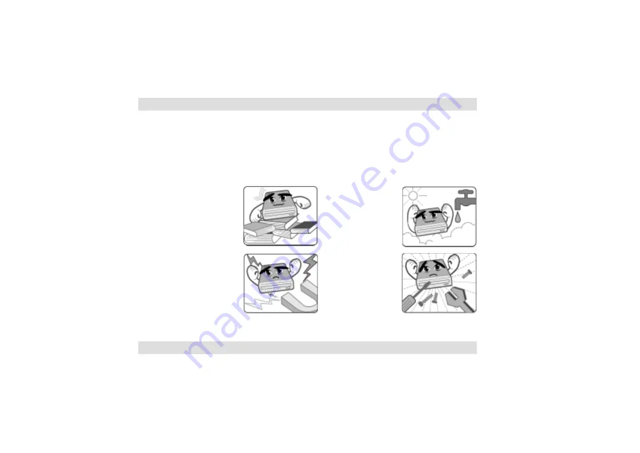
Do not attempt to
disassemble or
repair the drive.
Opening the drive
may result to
exposure to laser
radiation.

Do not use or place
this device near
magnetic fields,
televisions, or radios
to avoid electronic
interference that
affects drive
performance.

Do not place this
device under direct
sunlight, or in humid
or damp places.

Do not place this
device in an unstable
position, or on
vibrating surfaces.

Installation notices

Summary of Contents for CRW-5232AS

Page 1: ... CRW 5232AS 52x 32x 52x CD RW Drive E1456 User Guide Revised Edition V2 December 2003 ...

Page 2: ...90 7698 ASUS COMPUTER INTERNATIONAL America Address 44370 Nobel Drive Fremont Technical Support CA 94538 USA Tel General 1 502 995 0883 Fax 1 502 608 4555 Notebook 1 501 739 3777 E mail tmd1 asus com Support fax 1 502 933 8713 Web site usa asus com Support e mail tsd asus com ASUS COMPUTER GmbH Germany and Austria Address Harkort Str 25 D 40880 Technical Support Ratingen Germany Telephone 49 2102 ...

Page 3: ...OF SUCH DAMAGES ARISING FROM ANY DEFECT OR ERROR IN THIS DOCUMENTATION OR PRODUCT Product warranty or service will not be extended if 1 the product is repaired modified or altered unless such repair modification of alteration is authorized in writing by ASUS or 2 the serial number of the product is defaced or missing Products and corporate names appearing in this documentation may or may not be re...

Page 4: ...tices 6 Safety information 8 Installation notices 8 Using the device 9 Conventions used in this guide 10 Package contents 11 Welcome 12 Product introduction 12 Specifications 13 Features 14 Front panel 22 Rear panel 24 Installation 26 System requirements 26 ...

Page 5: ...CRW 5232AS drive basics 33 Recommended media 33 Placing a disc into the drive 33 Ejecting a disc from the drive 35 Using the emergency eject pinhole 36 Using compact discs 38 Cleaning a disc 38 Handling a disc 38 Technical information 39 Environmental specifications 39 Electrical and audio specifications 40 Contents ...

Page 6: ...tal device pursuant to Part 15 of the FCC Rules These limits are designed to provide reasonable protection against harmful interference in a residential installation This equipment generates uses and can radiate radio frequency energy and if not installed and used in accordance with manufacturer s instructions may cause harmful interference to radio communications However there is no guarantee tha...

Page 7: ...shielded cables for connection of the monitor to the graphics card is required to assure compliance with FCC regulations Changes or modifications to this unit not expressly approved by the party responsible for compliance could void the user s authority to operate this equipment Canadian Department of Communications Statement This digital apparatus does not exceed the Class B limits for radio nois...

Page 8: ...rive Opening the drive may result to exposure to laser radiation Do not use or place this device near magnetic fields televisions or radios to avoid electronic interference that affects drive performance Do not place this device under direct sunlight or in humid or damp places Do not place this device in an unstable position or on vibrating surfaces Installation notices ...

Page 9: ...this situation occurs contact your retailer for help Do not use any evaporating solvents to clean the device If you accidentally sprayed any solvent on the device use a clean cloth to wipe it You may also use a neutral cleaner to dilute the solvent to easily wipe it from the device Try not to interrupt the supply of power while the device is in reading or writing mode Do not place damaged or warpe...

Page 10: ...mbols used throughout this guide WARNING DANGER Information to prevent injury to yourself when trying to complete a task CAUTION Information to prevent damage to the components when trying to complete a task IMPORTANT Information that you MUST follow to complete a task NOTE Tips and additional information to aid in completing a task ...

Page 11: ...r if any of the items is damaged or missing ASUS CRW 5232AS internal IDE drive IDE cable Mounting screw set Audio cable Emergency eject pin and instruction slip User Guide English and Traditional Chinese Multi language quick installation guide Software CD The above items are available in retail boxes only The package contents are subject to change without notice ...

Page 12: ...nstallation of this device Product introduction Specifications The CRW 5232AS has the following specifications Speeds 52X 48X 40X 32X 24X 16X 8X 4X writes 32X 24X 16X 12X 10X 8X 4X rewrites 52X reads maximum Interface ATAPI specification Technologies FlextraSpeed and FlextraLink Double Dynamic Suspension System II DDSSII Constant Angular Velocity Recording ...

Page 13: ... mm thick CD Audio CD ROM CD ROM XA CD I Mixed Mode CD ROM Photo CD CD Extra Video CD CD Text DVCD CD G Karaoke CD I trax Bootable CD Recording Format Disc At Once Track At Once Session At Once Packet Write OS Compatibility Windows 98 ME 2000 NT XP DOS 6 xx Linux operating system Power Supply DC 5 x 1 5 V DC 12 x 1 10 V Dimensions 149 w x 41 5 h x 171 2 d mm Mass 830 g ...

Page 14: ...er than common internal CD RW drives the ASUS CRW 5232AS is an ideal optical drive solution for mini PC systems The ASUS CRW 5232AS employs the ASUS FlextraSpeed and FlextraLink technologies to ensure an efficient and reliable data transfer and storage FlextraSpeed increases accuracy and reliability when rewriting across a wide range of disc media while FlextraLink prevents buffer underrrun proble...

Page 15: ...y dust fingerprints etc affect the recording characteristics of CD R and CD RW discs Due to these factors some discs may not be able to stand the high speed capabilities of the latest CD RW drives The FlextraSpeed technology solves this problem by automatic assessment of the disc quality and recording capability The recording speed is based on these factors If you use a high quality recording disc...

Page 16: ...used by an empty data buffer This CD RW drive technology allows continuous monitoring of the data buffer status during the write process Once the available data drops to approximately 1 of the total buffer capacity the drive stops recording and marks the last write position When new data is received from the host it is loaded to the data buffer and the laser is repositioned to link the new data wi...

Page 17: ...ansfer continues and fills buffer with sufficient data for writing Buffer Memory Write process continues until writing is complete Data Write Data Write Data Buffer Memory Data Data transfer slows down Buffer Memory Write process stops waits until there is enough data for writing Data Write Data Recording with FlextraLink Technology Conventional Recording FlextraLink Technology Solution ...

Page 18: ...CD RW drives In addition the DDSS II stabilizes the pick up head of the drive in both horizontal and vertical directions making tracking and focusing even more precise Like the DDSS the DDSS II vibration absoption structure contains a dynamic mass that can absorb the vibration caused by high revolution of spindle motor However the DDSS II moves the dynamic mass to be suspended to the chassis thus ...

Page 19: ...ASUS CRW 5232AS 19 DDSS DDSS II Design Structure ...

Page 20: ... a higher transfer rate when writing data to the outer tracks of the disc than to the inner tracks as the head traverses a longer linear path on the outer than the inner part of the disc Although the transfer rates vary and may not be at maximum depending on the part of the disc being written to the CAV method allows faster recording speed because the rotation speed does not have to change when th...

Page 21: ...ASUS CRW 5232AS 21 Speed 48x 40x 32x 24x 16x 8x 0x Time 52x CAV Recording Method ...

Page 22: ...he volume of the headphone connected to the drive by turning the dial to the left volume decreases or right volume increases 3 Disc Loading Tray This tray holds the disc Open the loading tray by pressing the STOP EJECT Button Place a CD on the tray with the label side up Press the STOP EJECT Button or push the front part of the tray to load the disc ...

Page 23: ...sc when theSTOP EJECT Button does not work due to power failure or software problems Insert the emergency eject pin or a paper clip into this hole to manually eject the tray and the disc Refer to page 36 for details 7 PLAY SKIP button Press this button when the drive is idle to start playing the first track of an audio disc if one is currently loaded in the drive When in PLAY mode press this butto...

Page 24: ...s for a digital signal output cable 10 Analog audio connector This connector is for an analog signal output cable 11 Jumper terminals These pins allow you to select either Master Slave or Cable Select mode for the CD ROM device Refer to page 28 for jumper terminal settings ...

Page 25: ...le to connect the drive to the IDE interface on the motherboard 13 Power connector This DC connector is for a 4 pin power cable from the system power supply The jumper pins on the leftmost part of the rear panel are factory test pins DO NOT cover these pins with jumperblocks ...

Page 26: ... 850 MHz or higher PC Windows 98 ME 2000 NT XP DOS 6 xx Linux operating system At least 64MB RAM 128MB recommended An empty 5 25 inch drive bay HDD empty storage capacity of 100MB or more Average seek time 20ms or less Transmission rate 2 MB s or more 1 Avoid using a hard disk that thermally calibrates during operation 2 Do not insert damaged or warped disc in the drive to avoid potential body inj...

Page 27: ...as either master or slave mode before installing it into the computer chassis Refer to next page for an explanation of each drive mode Select your desired mode by placing the jumper cap over the pins Put the jumper caps properly over the pins to avoid damage to the drive Jumper terminals ...

Page 28: ...e Cover the two pins labeled SL to set the CRW 5232AS drive as a slave device if your computer supports only two IDE devices If your computer supports four IDE devices this mode sets your CRW 5232AS drive as either Primary or Secondary Slave Cable Select Mode Cover the two pins labeled CS if your computer supports a Cable Select CSEL signal You need an exclusive interface cable for this mode Refer...

Page 29: ... CRW 5232AS drive Follow these steps to install the drive into the computer chassis Refer to your computer manual for specific instructions on opening the chassis and installing drives 1 Remove the cover of an empty 5 25 inch drive bay ...

Page 30: ...ASUS CRW 5232AS 2 Carefully insert the drive into the bay and push it inward until it is flushed to the chassis front panel The holes on the sides of the drive should align with the holes on the drive bay ...

Page 31: ... the drive package Use two screws on each side of the drive Depending on the space on your chassis you may need to connect the drive cables before securing the drive into the chassis For cable connections proceed to the following section Connecting the Drive Cables ...

Page 32: ...ture connect an audio interface cable to the 4 pin analog audio connector on the rear of the drive Connect the other end of the audio cable to the connector on the sound card or on the 4 pin CD connector on the motherboard All the cable plugs are slotted so that they fit in only one orientation If a plug does not fit in completely try reversing it DO NOT use too much force when fitting the cable p...

Page 33: ...ing discs are recommended for use with the CRW 5232AS drive CD R Mitsubishi Chemical Prodisc Ritek Taiyo Yuden TDK CD RW AMT CMC Mitsubishi Chemical Prodisc Ricoh Ritek Placing a disc into the drive 1 Press the STOP EJECT button on the front of the drive to eject the tray ...

Page 34: ...u are using a 12 cm disc place it on the outer circular border of the tray If you are using an 8 cm disc place it on the inner circular border 2 When the drive tray ejects out of the drive place the disc on the tray with the label printed side up ...

Page 35: ...to replace the tray inside the drive Ejecting a disc from the drive 1 Press the STOP EJECT button on the front of the drive to eject the tray 2 Carefully remove the disc from the tray 3 Press the drive STOP EJECT button or lightly push the center of the drive tray to load the tray back into the drive ...

Page 36: ...nto the emergency eject pinhole Using the emergency eject pinhole The emergency eject pinhole on the front panel of the drive allows you to manually eject the drive tray and remove a disc from the drive in case the supply of power to the computer is cut due to electrical power outage or the drive malfunctions Use the manual method only when the STOP EJECT button does not work Turn off your compute...

Page 37: ...ASUS CRW 5232AS 37 2 Carefully pull the tray out and remove the disc Do not force the tray open Wait until the eject pin has dislodged the tray to avoid breaking the tray panel ...

Page 38: ...ction when using compact discs These instructions will help you avoid damaging the discs and your drive Cleaning a disc Spray the disc with compressed air for about five seconds to get rid of the dust on a disc Handling a disc Hold a disc by the edges Do not touch the disc surface ...

Page 39: ... peak at 5 500 Hz Storage 2 0G peak at 10 500 Hz Impact Non operation 1 oct min no damage Less than 50G at 11ms half sine wave 3 shock each side Packaged 1 oct min no damage 91 cm high 1 corner 3 edges 6 surfaces Acoustic Access Mode 47 5 dBa TYP Read Mode 45 dBa TYP Reliability MTBF 100 000 power on hours ODC Read 20 of power on time ODC Write 1 of power on time Mean Time To Repair MTTR 30 minute...

Page 40: ...5 10 Ripple 150m Vpp 300m Vpp Rating 900mA 1500mA IO Terminal Power connector 4 pin 5V 12V ATAPI terminal 40 pin Audio out 4 pin analog 2 pin digital Audio No of channels 2 stereo Sampling frequency 44 1 kHz Quantization 16 bits Distortion 0 2 max at 1 kHz S N ratio 70 dB Line Out 0 70 V rms typical ...

Reviews: