ASUS AP5000 Installation Guide
27
III. Integration
Housing
III. Integration Procedures
Integrating with the housing
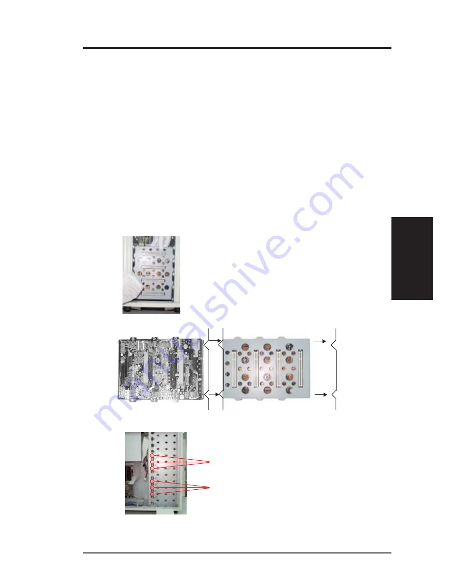
The housing could carry two Back Plane Boards to support eight SCSI
drives in total, and the first Back Plane Board has to be placed on lower
position of housing (Fig 3-33) and its two notches should connect to the
openings housing with no space in between (Fig 3-34), so that it could en-
large the force while inserting the drive bay. The second Back Plane Board
also has to use similar method mentioned above for the connection. Next,
fix them by screwing in the back and front of hosing as shown in Fig 3-35.
Finally connect SCSI cables and power cables to the Back Plane Boards,
and fix the SCSI cable on the cable clamps to prevent the conflict of re-
moval or installation of Fan Frame (Fig 3-36)
Connecting the SCSI cables
If you are installing one back plane board into the system, connect the SCSI
cable connector to the on-board SCSI connector directly.
If you are installing two back plane boards into the system, insert another
SCSI card and connect the two SCSI cables to it.
Fig 3-33: Place the first back plane board outside in the system from the front door.
Fig 3-34: Installing the second back plane board
Fig 3-35: Secure the two back plane boards onto the chassis
Second back plane board
First back plane board
Housing
The screws of the second back plane board
The screws of the first back plane board


