background image

22

ASUS AP5000 Installation Guide

III. Integration Procedures

III. Integration

Procedures

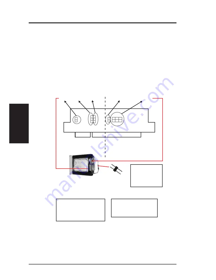
Fig 3-21: Jumper Location & Cabling with non SAF-TE Features

NON SAF-TE back plane boards

To install a slot card for a non SAF-TE back plane board, three cables connect to slot
card shown below, one (SCSI_ID) for SCSI device and the other two (KEY and
PLED) for drive bay. And for the two unconnected cables; SLED and ALED_IN
cables, they should be connected together, so that the SCSI device access status will
present to Light-2 (STATUS LED) of drive bay directly without going through the
slot card, because there is no function for this two jumper on slot card if the Back
Plane Board is non SAF -TE.

CAUTION

* PLED cable, 3-wire (Orange/Black/

Green), connects Green to position #1 of
PLED jumper.

* KEY cable, 2-wire (Black/Red) connects

Black to position #1 of KEY jumper.

* SCSI_ID cable, 8-wire, connects between

SCSI_ID jumper of slot card and ID
jumper of SCSI drive. Be sure their SCSI
ID matched

KEY

SLED

PLED

ALED_IN

SCSI_ID

1              1   1

Jumpers for Drive Bay

Jumpers for SCSI Drive

SLED and ALED_IN
cables link together in
between by this jumper. The
direction should be Green
wire of SLED cable to Red
wire of ALED-IN cable.

Summary of Contents for AP5000

Page 1: ...R AP5000 Dual Pentium II Server Platform Installation Guide ...

Page 2: ... in this manual may or may not be regis tered trademarks or copyrights of their respective companies and are used only for identification or explanation and to the owners benefit without intent to infringe Intel LANDesk and Pentium are registered trademarks of Intel Corporation IBM and OS 2 are registered trademarks of International Business Machines Symbios is a registered trademark of Symbios Lo...

Page 3: ...RNATIONAL Marketing Address 6737 Mowry Ave Mowry Business Center Building 2 Newark CA 94560 USA Fax 1 510 608 4555 Email info usa asus com tw Technical Support Fax 1 510 608 4555 BBS 1 510 739 3774 Email tsd usa asus com tw WWW www asus com FTP ftp asus com tw pub ASUS ASUS COMPUTER GmbH Marketing Address Harkort Str 25 40880 Ratingen BRD Germany Telephone 49 2102 445011 Fax 49 2102 442066 Email i...

Page 4: ...ASUS AP5000 Installation Guide 4 This page was intentionally left blank ...

Page 5: ... CPU 17 Installing the memory 18 Installing a VGA or PCI add on card 18 Installing the ATX power switch and other signal pins 18 Closing the cover 19 CABLING 20 DRIVE SETUP 20 Installing a slot card 21 SAF TE back plane boards 21 NON SAF TE back plane boards 22 Indicator lights 23 Installing SCSI devices 24 Drive locations 24 BACK PLANE BOARD INSTALLATION 26 Integrating the DA BP4 1 S 26 Integrati...

Page 6: ...icular installation If this equipment does cause harmful inter ference to radio or television reception which can be determined by turn ing the equipment off and on the user is encouraged to try to correct the interference by one or more of the following measures Reorient or relocate the receiving antenna Increase the separation between the equipment and receiver Connect the equipment to an outlet...

Page 7: ...0 The AP5000 uses the P2L97 DS smart motherboard as its base to support dual Pentium II processor With a built inAGP slot theAP5000 can be both a server and workstation The following introductions will guide you to understand and build up such a best system AP5000 Two sections will be introduced as following Bare Bone Kits Overview Integration Procedure ...

Page 8: ...8 ASUS AP5000 Installation Guide I INTRODUCTION I INTRODUCTION This page was intentionally left blank ...

Page 9: ...ard HOUSING The housing of the AP5000 is ivory white Its front and back view after system assembly is shown below Fig 2 1 Front view of housing Fig 2 2 Back side of housing Power button Front door Device drive bay Key locker of front door Cover install remove locker Tower feet with wheel Redundant power supply Power connectors Parallel I O port Serial I O port II BARE BONE KITS II BARE BONE KITS ...

Page 10: ...t 1 Top USB Port 2 Bottom Programmable 2Mbit Flash ROM 4 PCI Slots 2 ISA Slots Parallel Top Hardware Monitor optional Multi I O Chip Floppy Disk Drive Connector Narrow Wide SCSI Connectors optional Adaptec s 7880 Fast Wide SCSI Chipset optional Intel PIIX4 PCIset Primary Secondary IDE Connectors PS 2 Mouse Top PS 2 K Board Bottom SEC CPU Slots Intel 440LX AGPset DIMM Sockets Accelerated Graphics P...

Page 11: ...l slot card connected together Fig 2 7 When the completed drive set plugs in the slot board of drive Bay and bus of DA BP4 will be connected to gether After that all the four SCSI ID of SCSI devices could be managed from the switches of Back Plane Board Fig 2 6 Moreover there are two models of Back Plane Boards available for none SAF TE and SAF TE which are named DA BP4 1 and DA BP4 1S SAF TE one ...

Page 12: ...ower of SCSI drive None SCSI drive SCSI connector Connector of wide SCS I DA BP4 1S SCSI ID could be managed from DA BP4 1 S refer to Fig 3 28 SCSI_ID cable 8 wire 68 pin wide SCSI cable PLED 3 pin Power LED SCSI_ID 8 pin ID jumper of SCSI drive Be sure the target SCSI ID is in the right order Jumper of device accessing ALED_IN cable 2 wire Red Black Access jumper of SCSI drive ALED_IN 2 pin PLED ...

Page 13: ...d with none SAF TE Back Plane Board Items Functions Cables Uses Connect To Golden Finger Bus of Slot Card None DA BP4 1 Power Cable Power of SCSI drive None SCSI drive SCSI connector Connector of wide SCS I DA BP4 1 SCSI ID could be managed from DA BP4 1 S refer to Fig 3 28 SCSI_ID cable 8 wire 68 pin wide SCSI cable SLED 3 pin None None None SCSI_ID 8 pin ID jumper of SCSI drive Be sure the targe...

Page 14: ...14 ASUS AP5000 Installation Guide II BARE BONE KITS II BARE BONE KITS This page was intentionally left blank ...

Page 15: ...stallation Cabling Device Drives Installation and Back Plane Board Installation SYSTEM UNIT System assembly steps are as follows 1 Open cover 2 Remove fan frame 3 Install the motherboard 4 Install the CPU memory and add on cards Opening the cover Remove the four screws in the back of the system Fig 3 1 Follow the direction on the cover locker to release Fig 3 2 and remove the cover of housing Fig ...

Page 16: ... frame module Fig 3 4 Put the motherboard sup port spacer in order to balance the power of plugging add on and CPU cards Fig 3 5 then place the motherboard into the housing Fig 3 6 Next screw the motherboard into the housing Fig 3 7 Please do not over tighten as this may damage the surface of the motherboard Fig 3 6 Place the motherboard Fig 3 5 Put in Main Board Spacer III INTEGRATION III INTEGRA...

Page 17: ...he memory and power I O cables Next install the memory power cable serial parallel VGA brackets and HDD FDD cable Fig 3 8 For more details about cable paths of device drives refer to Cabling p 20 Insert the CPU into the retention module If you only have one CPU insert a termination card into the other CPU slot III INTEGRATION III INTEGRATION Power connector Memory I O ports and brackets SCSI hard ...

Page 18: ...t Installing theATX power switch and other signal pins Refer to the P2L97 DS user s manual to install the ATX power switch pin system indicator pin and IDE device indicator pin Fig 3 13 Fig 3 12 Insert a VGA PCI add on card Fig 3 11 Insert the SDRAM Secure the power switch next to the FDD with screws Fig 3 13 III INTEGRATION III INTEGRATION IDE device indicator pin System power indicator pin ATX p...

Page 19: ...gration Procedures Closing the cover Follow the figures below Fig 3 15 3 16 3 17 to complete the hard ware installation Fig 3 17 Lock the cover Fig 3 15 CPU and motherboard installed Fig 3 16 Replace the cover III Integration Closing the Cover ...

Page 20: ...means of indicator light on drive bay are quite complex This section shows that the installation of slot card with drive bay the specification of indica tor light device installation and the recommendation of drive position on the housing CABLING There are three sets of cables and their locations are indentified in Fig 3 18 and Fig 3 19 Fig 3 18 Cable locations III Integration Connections Cabling ...

Page 21: ...N cable 2 wire connects be tweenALED_INofslotcardandaccess jumper of SCSI drive Fig 3 20 Jumper Location Cabling with SAF TE Features Installing a slot card To install a slot card with a Hot Swap drive bay there are two types of cabling methods as shown below One is for SAF TE back plane boards Fig 3 20 another is for none SAF TE back plane boards Fig 3 21 SAF TE back plane boards To install SAF T...

Page 22: ...l present to Light 2 STATUS LED of drive bay directly without going through the slot card because there is no function for this two jumper on slot card if the Back Plane Board is non SAF TE CAUTION PLED cable 3 wire Orange Black Green connects Green to position 1 of PLED jumper KEY cable 2 wire Black Red connects Black to position 1 of KEY jumper SCSI_IDcable 8 wire connectsbetween SCSI_ID jumper ...

Page 23: ...cator Specification of Non SAF TE Device Status Indicator Light 1 Indicate Light 2 Power ON OFF Drive Access ON Blink Key Lock Light 2 SLED Light 1 PLED Fig 3 22 Indicator Light of Drive Bay Device Status Indicator Light 1 Indicate Light 2 Color of Light No Error OFF NO NO Faulty ON OFF Red Identify Alternating Fast Blink 3 sec Red Green between Light 1 and Light 2 Rebuild OFF Fast Blink 3 sec Gre...

Page 24: ... pin SCSI ID cable is connecting with correspondent SCSI ID on both SCSI drive and slot card Fig 3 24 Finally screw in the SCSI drive with drive bay Fig 3 25 Fig 3 23 Integrated Drive Bay Fig 3 24 Necessary Cables Connect to SCSI device both Front and Back Fig 3 25 Screw in device on Drive Bay Drive locations The recommendation of drives location is that first top drive used for floppy second for ...

Page 25: ...lled please close or lock the front door of the AP5000 to protect them Fig 3 26 Drive setup Fig 3 27 3 types of drive covers Hot Swap drive bay does not require a cover Fig 3 28 Fig 3 29 To remove a drive cover first release the two retainers on each side of the cover by pressing them in and then out toward the front with a screwdriver Fig 3 28 Carefully remove the drive cover from the front using...

Page 26: ... ASUS DA BP4 1 S contains one SCSI connector that will connect to on board SCSI port of AP5000 and its back has four PCI slots connecting to slot card of drive bay to support 4 SCSI drives There is a box come with the Back Plane Board for mounting it onto the housing Below will show the DA BP4 1 S with the box Fig 3 30 Front Site View of DA BP4 1 S Switches Specification SCSI ID ID3 ID2 ID1 ID0 0 ...

Page 27: ... Fig 3 35 Finally connect SCSI cables and power cables to the Back Plane Boards and fix the SCSI cable on the cable clamps to prevent the conflict of re moval or installation of Fan Frame Fig 3 36 Connecting the SCSI cables If you are installing one back plane board into the system connect the SCSI cable connector to the on board SCSI connector directly If you are installing two back plane boards ...

Page 28: ...es Fig 3 38 Fig 3 37 Installing the disk drive bay to the back plane board Lift the hold bar up to a 45 angle Fig 3 37 Push in firmly to ensure that the bay is connected to the back plane board Fig 3 38 Cables Power cable Cable clamp SCSI cable Fig 3 36 Be sure the cable clamps are fixed ...

Page 29: ...Fig 3 39 Replacements For a defective power system 1 Remove the side cover Fig 3 40 2 Remove the power cable from the cable clamp Fig 3 41 3 Unscrew the six screws Fig 3 42 4 Carefully remove the power supply from the left side Fig 3 43 Fig 3 40 Fan Power Switches Module Handle Power Connector Power Reset Button ...

Page 30: ...30 ASUS AP5000 Installation Guide III Integration Remove Driver III Integration Procedures Fig 3 41 Fig 3 43 Fig 3 42 ...

Page 31: ... the power sup ply indicates that there is a defective module 2 To stop the beeping sound press the red button located on the power supply Fig 3 44 3 Unscrew the screw and release the module Fig 3 45 4 Grab the module handle and pull the power supply out towards you Fig 3 46 5 Replace with a new module 6 Secure the new module with screws Fig 3 44 Fig 3 45 Reset Button ...

Page 32: ...32 ASUS AP5000 Installation Guide Fig 3 46 III Integration Remove Driver III Integration Procedures ...

Reviews: