background image

Chapter 4:  Motherboard information

4-8

4.3

Connectors

This section describes the internal connectors on the motherboard.
Refer to section “1.4  Rear panel features” for information on the
external (rear panel) connectors.

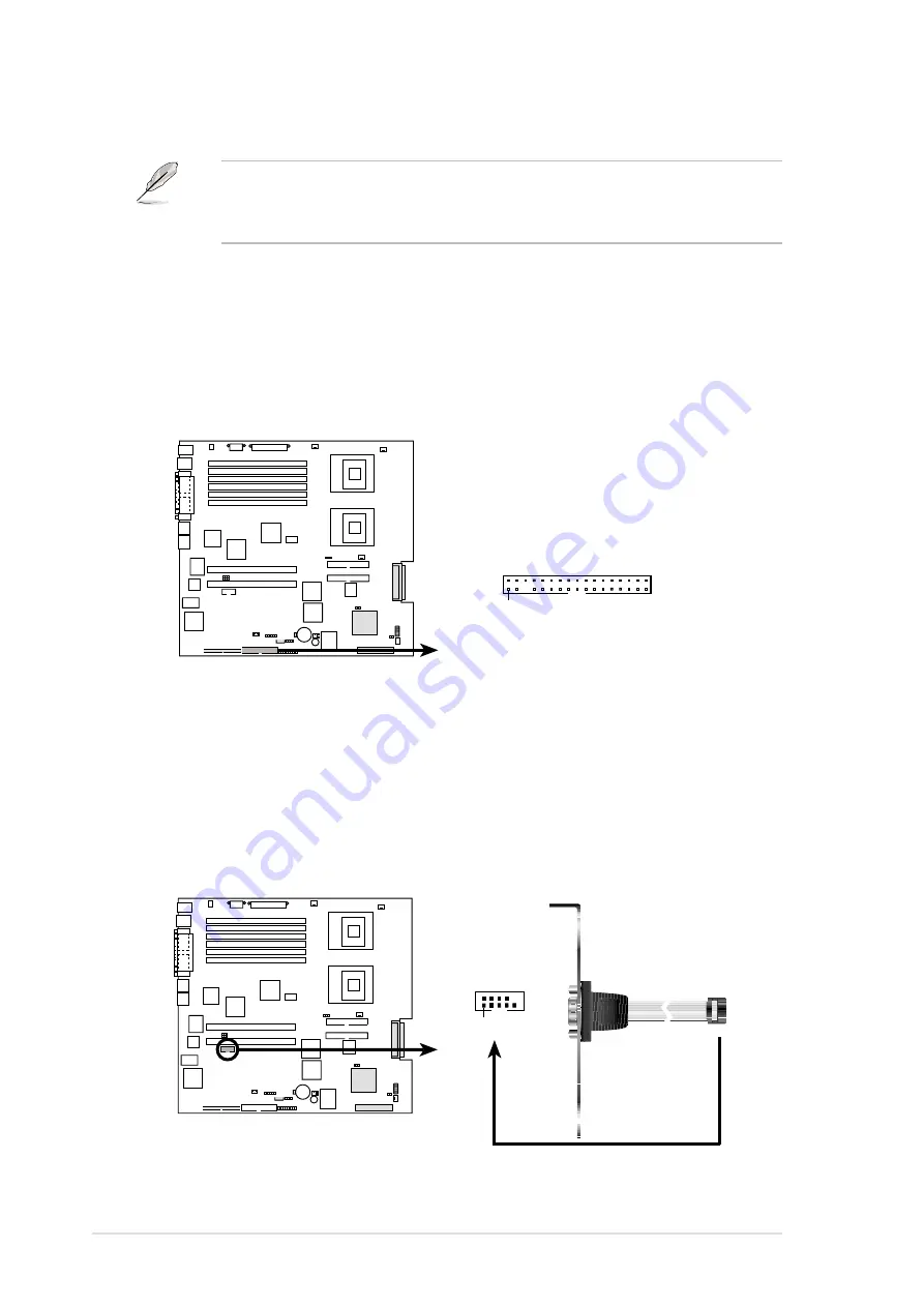
1. Floppy disk drive connector (34-1 pin FLOPPY1)

This connector supports the provided floppy drive ribbon cable. After
connecting one end to the motherboard, connect the other end to the
floppy drive. (Pin 5 is removed to prevent incorrect insertion when
using ribbon cables with pin 5 plug).

PR-DLS533

NOTE: Orient the red markings on
the floppy ribbon cable to PIN 1.

PR-DLS533 Floppy Disk Drive Connector

PIN 1

FLOPPY

PR-DLS533

PR-DLS533 Serial COM2 Connector

PIN 1

2. Serial port 2 connector (10-1 pin COM2)

This connector accommodates a second serial port using an optional
serial port bracket. Connect the bracket cable to this connector then
install the bracket into a slot opening at the back of the system chassis.

Summary of Contents for AP2400R-E1

Page 1: ...Dual Intel Xeon 4 2U Rackmount Server 533 400MHz Front Side Bus AP2400R E1 User Guide ...

Page 2: ...ion of business and the like even if ASUS has been advised of the possibility of such damages arising from any defect or error in this manual or product Specifications and information contained in this manual ae furnished for informational use only and are subject to change at any time without notice and should not be construed as a commitment by ASUS ASUS assumes no responsibility or liability fo...

Page 3: ...er 2 4 2 1 4 Installing the top cover 2 5 2 1 5 Removing the air duct 2 6 2 1 6 Installing the air duct 2 7 2 2 Central Processing Unit CPU 2 9 2 2 1 Removing the CPU heatsink 2 9 2 2 2 Installing a CPU 2 10 2 2 3 Installing the CPU heatsink 2 12 2 3 System memory 2 13 2 3 1 Memory configurations 2 13 2 3 2 Installing a DIMM 2 14 2 3 3 Removing a DIMM 2 14 2 4 Hard disk drives 2 15 2 5 Expansion c...

Page 4: ...hapter 3 Installation options 3 1 3 1 Rackmount rail kit items 3 2 3 2 Attaching the rails to the server 3 3 3 3 Attaching the rack rails 3 4 3 4 Rackmounting the server 3 6 Chapter 4 Motherboad information 4 1 4 1 Motherboard layout 4 2 4 2 Switches and jumpers 4 4 4 2 1 Switches 4 4 4 2 2 Jumpers 4 5 4 3 Connectors 4 8 Chapter 5 BIOS Setup 5 1 5 1 Managing and updating your BIOS 5 2 5 1 1 Creati...

Page 5: ... 5 Power Menu 5 23 5 5 1 Power Up Control 5 25 5 5 2 Hardware Monitor 5 27 5 6 Boot Menu 5 28 5 6 1 Boot Configuration 5 30 5 7 Server Menu 5 31 5 8 Exit Menu 5 32 Appendix References A 1 A 1 Power supply A 2 A 1 1 General description A 2 A 1 2 Specifications A 3 A 2 Qualified Vendors List QVL A 4 A 3 Troubleshooting A 6 ...

Page 6: ... harmful interference to radio or television reception which can be determined by turning the equipment off and on the user is encouraged to try to correct the interference by one or more of the following measures Reorient or relocate the receiving antenna Increase the separation between the equipment and receiver Connect the equipment to an outlet on a circuit different from that to which the rec...

Page 7: ...fied or experienced engineers Before operating the server carefully read all the manuals included with the server package Before using the server make sure all cables are correctly connected and the power cables are not damaged If any damage is detected contact your dealer as soon as possible To avoid short circuits keep paper clips screws and staples away from connectors slots sockets and circuit...

Page 8: ...the barebone server 4 Chapter 4 Motherboard information This chapter includes the motherboard layout and brief descriptions of the jumpers and internal connectors 5 Chapter 5 BIOS setup This chapter tells how to change the system settings through the BIOS Setup menus 6 Appendix References This appendix includes additional information that you may refer to when configuring your barebone server WARN...

Page 9: ...1 1 ASUS AP2400R E1 2U barebone server This chapter describes the general features of the barebone server It includes sections on front panel and rear panel specifications Chapter 1 Product introduction ...

Page 10: ...ackmount chassis with ASUS PR DLS533 Rack motherboard 500W redundant power supply 115V 230V slim optical drive slim floppy disk drive chassis fan HDD fan hot swap SCSI HDD trays SCSI backplanes front bezel CPU heatsink 2 pcs AC power cable System screws and cables Rackmount rail kit Accessory box AP2400R E1 user guide AP2400R E1 support CD includes ASWM TrendMicro ServerProtect CD AR22 chassis ear...

Page 11: ...LAN controller Intel 82540EM 32 bit Gigabit LAN controller VGA ATI RAGE XL PCI based VGA controller Supports 8MB display memory SCSI LSI 53C1030 64 bit 133MHz Ultra320 SCSI controller Expansion slots 3 x full length 64 bit 133MHz 3V PCI X slots 1 x low profile 64 bit 133MHz 3V PCI slot Storage 8 x 3 5 inch hot swappable HDD bays 1 x slim Teac CD ROM drive 1 x slim 1 44MB floppy drive Front I O 2 x...

Page 12: ...ves and two USB ports are located on the front panel Power supply LEDs PS 2 keyboard port PS 2 mouse port VGA port Gigabit LAN ports Serial port AC power sockets Location switch Location LED Expansion slots USB 1 1 ports External SCSI port Rear fans Redundant power supply modules Hot swappable HDD bays Slim optical drive Reset button USB 1 1 ports Power button Location switch Slim floppy drive Fro...

Page 13: ... with heatsink 6 CPU1 socket with heatsink 7 7 x system fans 8 SCSI backplane 1 9 SCSI backplane 2 10 SCSI backplane 3 11 3 x HDD bays 12 Top Slim optical drive Mid Slim floppy drive Bottom 2 x HDD bays 13 3 x HDD bays 1 2 5 6 8 9 10 3 7 4 11 12 13 PCI X card cage The air duct lies on top of the motherboard components Remove the air duct to access the components Refer to section 2 1 4 Removing and...

Page 14: ...y status Description Power LED ON System power ON HDD Access LED OFF No activity Blinking Read write data into the HDD Message LED OFF System is normal no incoming event Blinking ASWM indicates a HW monitor event Location LED OFF Normal status ON Location switch is pressed Press the location switch again to turn off LAN1 LED OFF No 64 bit Gbit LAN connection Blinking LAN is transmitting or receivi...

Page 15: ...ASUS AP2400R E1 2U barebone server 2 1 This chapter lists the hardware setup procedures that you have to perform when installing or removing system components Chapter 2 Hardware setup ...

Page 16: ...e hot swap HDDs optical drive and floppy drive Remove the chassis cover to access the internal components or if you wish to install system devices 2 1 1 Removing the front bezel To remove the front bezel 1 Hold the sides of the front bezel then slightly press the middle part to disengage it from the front panel 2 Pull the bezel from the front panel Press here to release ...

Page 17: ...p up the front corners of the top cover then lift the front half The front corners of the cover have dents that match those on the chassis These dents provide a holding mechanism and keeps the cover in place even when the sliding locks are released If you wish to access the hot swappable system fans backplanes optical drive and floppy drive you only need to open the front half of the top cover Mat...

Page 18: ...r open slide the cover toward the rear panel until the mid hooks on the top cover are disengaged Thumbscrew To remove the top cover 1 Loosen the thumbscrew that secures the top cover on the rear part of the chassis You need to open the front half of the top cover before you can remove the entire top cover Refer to section 2 1 1 Opening the top cover front half for instructions ...

Page 19: ... top cover over the chassis as shown and align the mid hooks with the notches on the sides 4 Push the sliding locks toward the front edge to secure the top cover in place 3 Flip down the front part of the top cover 2 Slide the cover toward the front panel until the mid hooks are locked into the notches 1 2 ...

Page 20: ...remove the air duct 1 Carefully route the cables that may interfere when removing the air duct Be careful not to pull off or break any cables while removing the air duct 2 Hold the rear part of the air duct and press it for about a fraction of an inch just enough to tilt the front end 3 When tilted carefully pull the air duct upward to release it from the chassis ...

Page 21: ...ber pads underneath the air duct and ensure that they are in place otherwise the air duct will not fit properly 4 Fit the other end of the air duct making sure that no power cable is strayed under it Plastic clips to grip the metal strips on the fan cage Flat rubber pads should match the top of the two heatsinks Vertical rubber pads should fit the spaces between the two heatsinks Metal strips to f...

Page 22: ...up 2 8 5 When the air duct is in place arrange the power cable cluster to fit the space beside the air duct 6 Flatten the power cable that runs across the air duct When properly installed the air duct should appear as shown ...

Page 23: ...steps to remove the heatsinks before proceeding to the next section To remove the CPU heatsink 1 Disconnect the fan cable from the connector on the motherboard 2 Use a Phillips cross screwdriver to loosen the four screws that secure the heatsink until it is released 3 Carefully lift the heatsink from the motherboard You need to remove the pre installed CPU heatsink before installing a CPU You don ...

Page 24: ...damage the CPU 1 The motherboard supports either one or two CPUs If you are installing only one CPU you MUST install it in CPU socket 1 2 If you are installing two CPUs install in the CPU socket 2 first CPU onboard LED This warning LED LED1 lights up if you installed two CPUs of different type voltage You must install identical CPUs on this motherboard PR DLS533 PR DLS533 Onboard LED LED1 ON CPU T...

Page 25: ...ts in place Make sure that the socket lever is pushed back all the way Otherwise the CPU does not fit in completely The CPU fits only in one correct orientation DO NOT force the CPU into the socket to prevent bending the pins and damaging the CPU 4 Carefully push down the socket lever to secure the CPU The lever clicks on the side tab to indicate that it is locked 5 Apply the thermal interface mat...

Page 26: ...to completely secure the heatsink 3 Connect the thermistor cable to the 2 pin cable from the mid fan board 2 2 3 Installing the CPU heatsink To install the CPU heatsink 1 Carefully place the heatsink on top of the installed CPU CPU1 with the thermistor cable near the connector labeled CPUFAN1 4 Follow steps 1 and 2 to install the second CPU heatsink The second CPU heatsink does not have a thermist...

Page 27: ...A1 you must install the same type of 512MB module into DDRA2 The same rule applies to pairs DDRB1 DDRB2 and DDRC1 DDRC2 An exception to this rule allows you to install one DIMM into the DDRA1 socket the socket closest to the ATX power connector Installing a single DIMM into any other socket would not work The following table lists the DIMM socket pairs and the memory modules that you can install D...

Page 28: ...IMM on the socket such that the notch on the DIMM matches the break on the socket 3 Firmly insert the DIMM into the socket until the retaining clips snap back in place and the DIMM is properly seated 1 Simultaneously press the retaining clips outward to unlock the DIMM 2 Remove the DIMM from the socket 2 3 3 Removing a DIMM Follow these steps to remove a DIMM Support the DIMM lightly with your fin...

Page 29: ...hing the spring lock to the right then pulling the tray lever outward The drive tray ejects slightly after you pull out the lever 3 Firmly hold the tray lever and pull the drive tray out of the bay 4 An empty drive tray includes a metal bracket for support Use a Phillips cross screwdriver to remove the bracket if you wish to install a hard disk in the drive tray Metal bracket ...

Page 30: ...ws two on each side 6 Carefully insert drive tray and push it all the way to the depth of the bay until just a small fraction of the tray edge protrudes 7 Push the tray lever until it clicks and secures the drive tray in place The drive tray is correctly placed when its front edge aligns with the bay edge ...

Page 31: ...ort three full length expansion cards 2 5 1 Installing a low profile expansion card To install a low profile expansion card 1 Firmly hold the card by the edges and align the card connector to the PCI X slot PCI X1 PCI X slots inside the PCI cage PCI X2 2 Push the card connector into the slot until it fits in place 3 Secure the card bracket with a screw Card screw ...

Page 32: ...e cage 2 Firmly hold and lift the cage as shown to completely detach it from the chassis then turn it over to access the power connector To install a full length expansion card 1 Disengage the PCI cage from the chassis by lifting the cage handle to about 45o angle The full length expansion cards are inside the PCI cage If you wish to install full length expansion cards you need to remove the PCI c...

Page 33: ...t steps 5 to 8 if you wish to install other PCI X cards 4 Place the cage on a flat stable surface with the slot facing up and prepare the card that you wish to install Internal view of PCI cage Install PCI X cards in the following order first PCI X card top slot furthest from motherboard second PCI X card middle slot third PCI X card bottom slot nearest the motherboard Exceptions 1 Install a RAID ...

Page 34: ...cage close enough to avoid pulling the power cable 10 Before re installing the PCI cage into the chassis check that all cables on the PCI cage bay are properly connected and routed Cables on the PCI cage bay 11 Take note of the two pegs on the PCI cage bay These pegs should match the holes on the cage to make sure it fits in place PCI cage pegs ...

Page 35: ... place 14 Ensure that the PCI cage card golden connectors completely fit the slot If properly installed the top of the PCI cage aligns with the top edge of the rear panel 12 Position the PCI cage into the bay making sure that the pegs go into the holes on the front of the cage and the dents on the rear part match those on the chassis ...

Page 36: ...s IRQ assignments for this motherboard IRQ Priority Standard Function 0 1 System Timer 1 2 Keyboard Controller 2 N A Programmable Interrupt 3 11 Communications Port COM2 4 12 Communications Port COM1 5 13 Sound Card sometimes LPT2 6 14 Floppy Disk Controller 7 15 Printer Port LPT1 8 3 System CMOS Real Time Clock 9 4 ACPI Mode when used 10 5 IRQ Holder for PCI Steering 11 6 IRQ Holder for PCI Steer...

Page 37: ...tors from MB to rear fan board 2 24 pin 8 pin power connectors from power supply to MB 3 Floppy drive connector from MB to floppy drive 4 SMBus connector from MB to SCSI board 5 PANEL connectors from MB to front panel 6 Chassis intrusion connector from MB to front panel 7 SCSI B connector from MB to SCSI board or to external SCSI port 8 SCSI A connector from MB to SCSI board 9 Secondary IDE from M...

Page 38: ... 72 bit 184 pin module DDR DIMMC1 64 72 bit 184 pin module DDR DIMMC2 64 72 bit 184 pin module Secondary IDE SYSFAN3 COM2 Super I O PS 2 T Mouse B Keyboard USB1 USB2 COM1 VGA RJ 45 LAN 2 PCI X1 64 bit 133MHz 3V CPUFAN1 SYSFAN2 IPMI CR2032 3V Lithium Cell CMOS Power PANEL SMB R452 VGA RAM CPUFAN2 SYSFAN1 SCSI A RJ 45 LAN 1 Intel 82544GC Gigabit Ethernet CLKSW IGLAN_EN LAN_SW mPGA 604 mPGA 604 Serve...

Page 39: ...us cable to SCSI BP 3 J5 SCSI BP 3 SMBus cable to mid fan board J4 4 pin power cable from power supply SCSI cable from motherboard or SCSI cable from SCSI BP 1 SCSI Terminator or SCSI cable from motherboard or SCSI cable to SCSI BP 2 J5 SCSI BP 1 SMBus cable from motherboard SCSI BP 2 SMBus cable from SCSI BP 1 J4 SCSI BP 3 SMBus cable from SCSI BP 2 J5 J6 jumper J3 jumper J1 jumper ...

Page 40: ... connectors used by SCSI backplane boards No RAID card SCSI cable from MB SCSI A connector SCSI cable to SCSI BP 2 SCSI cable from SCSI BP 1 Terminator Terminator SCSI cable from MB SCSI B connector SCSI BP 3 SCSI BP 2 SCSI BP 1 Rear panel SCSI A connector SCSI B connector SCSI BP 1 SCSI BP 3 SCSI BP 2 ...

Page 41: ...I B connector connects to external SCSI port on the rear panel SCSI A connector connects to SCSI BP 3 RAID card installed on PCI X riser card inside PCI cage SCSI BP 1 SCSI BP 3 SCSI BP 2 External SCSI connector on the rear panel SCSI cable from RAID card connector SCSI cable to SCSI BP 2 SCSI cable from SCSI BP 1 Terminator Terminator SCSI cable from MB SCSI A connector SCSI BP 3 SCSI BP 2 SCSI B...

Page 42: ...connector no connection SCSI BP 1 SCSI BP 3 SCSI BP 2 SCSI B connector connects to external SCSI port on the rear panel RAID card installed on PCI X riser card inside PCI cage External SCSI connector on the rear panel SCSI cable from RAID card channel 1 SCSI cable to SCSI BP 2 SCSI cable from SCSI BP 1 Terminator SCSI BP 3 SCSI BP 2 SCSI BP 1 Rear panel SCSI cable from RAID card channel 2 Terminat...

Page 43: ...gs SCSI BP 1 SCSI BP 2 SCSI BP 3 8 10 9 4 6 5 0 2 1 SCSI slot 1 SCSI slot 2 SCSI slot 3 Front panel SCSI BP 1 SCSI BP 2 SCSI BP 3 SCSI slot 1 0 4 8 SCSI slot 2 2 6 10 SCSI slot 3 1 5 9 SAF TE 15 12 13 SCSI card if present 7 Rear panel SCSI BP 2 SCSI BP 1 SCSI BP 3 J1 J6 J3 J1 J6 J3 J1 J6 J3 ...

Page 44: ... 3 SCSI BP 1 SCSI BP 2 Mid fan board FANBPC AR21 SMBus J4 SMBus cable from MB SMBus connector J4 J5 J4 J5 J4 SCSI BP 3 SCSI BP 2 SCSI BP 1 SMBus cable to mid fan board SMBus connector J4 P9 plug from power supply P7 plug from power supply P6 plug from power supply J5 Rear panel ...

Page 45: ...FANBP AR21 located underneath the 7 hot swap fans 1 2 3 4 5 6 7 Connect the mid fan board FANBPC AR21 Mid fan board FANBPC AR21 SMBus cable from SCSI BP 3 To main fan board FANBP AR21 P3 plug from power supply 2 pin thermistor cable from CPU heatsink 1 6 1 pin cable from FAN60M J1 connector ...

Page 46: ...nnects to FAN60M board Rear fan board FAN60BPC Rear fan cables Fan interface board FAN60M Connects the FAN60BPC board Connects to CPU_FAN1 on MB Connects to SYS_FAN3 on MB Connects to J2 on FANBPC AR21 Side facing rear panel Side facing front panel ...

Page 47: ...the LED color turns orange the fan is faulty and should be replaced To remove an 80mm hot swap fan 1 Stand in front of the system and open the top cover 2 Use the thumb and index finger of your right hand to flip up the right handle and the thumb and index finger of your left hand to flip up the left handle of the fan that you wish to remove 3 Firmly hold the handles and pull up the fan until it i...

Page 48: ... the power supply module out of the chassis 2 Hold the module lever and press the latch on the inner side to release the module The module lever bends down about half an inch as the power supply slides out 4 Repeat steps 2 to 3 to remove the other module 2 7 3 Power supply modules The barebone system ships with one power supply module You may purchase a second power supply module for redundancy ...

Page 49: ... and signal cables connected to the rear of the drives 2 Loosen the thumbscrew that secures the drive bracket to the chassis The optical drive is attached to the top of the bracket and the floppy drive to bottom 3 Slide the drive bracket toward the SCSI backplanes to release it from the chassis then carefully pull it out of the drive bay ...

Page 50: ...nnected to the rear of the board 2 Remove the three screws the secure the board to the chassis 3 Carefully remove the board out of the chassis When removed the LED and switch board appears as shown The LEDs and switches on the board correspond to the LEDs and buttons on the system front panel Front side Front panel LEDs and buttons Rear side ...

Page 51: ...2 7 6 SCSI backplanes To uninstall a SCSI backplane 1 Disconnect all cables connected to the rear of the SCSI backplane 2 Carefully push the backplane upward to remove it from the chassis 3 Repeat steps 1 to 2 to remove the other backplanes ...

Page 52: ...Chapter 2 Hardware setup 2 38 ...

Page 53: ...ASUS AP2400R E1 2U barebone server 2 1 This chapter describes how to install optional components and devices into the barebone server Chapter 3 installation options ...

Page 54: ... items Your rackmount rail kit package contains one pair of rack rails for the rack two pairs of server rails for the server to accommodate different sizes of rack 12 pairs of nut and bolt type screws Front end Rear end Server rails Rack rails Nuts and bolts ...

Page 55: ...ks on the side of the chassis 2 Position a server rail parallel to the side of the chassis and match each of the five hooks to the holes on the rail Side hook locked to rail hole Side hooks 3 Secure the server rail to the with a screw 4 Repeat steps 1 to 3 to attach the second server rail to the other side of the chassis ...

Page 56: ...3 Remove the screws from the corresponding 2U space on the rack rear 4 Measure the depth of the rack to determine the length of the rack rails 5 Take three pieces of rack rail consisting of the middle piece one front end with stopper tab and one rear end without stopper tab Assemble the rack rail to a length depending on the rack depth 6 Secure the pieces together with two pairs of nut and bolt sc...

Page 57: ...easure the rack rail when assembled to make sure that it fits the rack 9 Secure the front end of the rail with two rack screws 10 Secure the rear end of the rail with two rack screws 11 Repeat steps 5 to 9 to assemble and attach the second rack rail Front end with stopper Rear end without stopper ...

Page 58: ...Chapter 3 Installation options 3 6 3 4 Rackmounting the server To mount the server to the rack align the server rails with the rack rails and push the server to the depth of the rack as shown ...

Page 59: ...ASUS AP2400R E1 2U barebone server 2 1 This chapter includes the motherboard layout and brief descriptions of the jumpers and internal connectors Chapter 4 Motherboard info ...

Page 60: ...64 72 bit 184 pin module DDR DIMMB1 64 72 bit 184 pin module DDR DIMMB2 64 72 bit 184 pin module DDR DIMMC1 64 72 bit 184 pin module DDR DIMMC2 64 72 bit 184 pin module Secondary IDE SYSFAN3 COM2 Super I O PS 2 T Mouse B Keyboard USB1 USB2 COM1 VGA RJ 45 LAN 2 PCI X1 64 bit 133MHz 3V CPUFAN1 SYSFAN2 IPMI CR2032 3V Lithium Cell CMOS Power PANEL SMB R452 VGA RAM CPUFAN2 SYSFAN1 SCSI A RJ 45 LAN 1 In...

Page 61: ...nnector 10 1 pin COM2 4 8 3 IDE connectors 40 1 pin PRI_IDE blue SEC_IDE black 4 9 4 Chassis intrusion connector 4 1 pin CHASSIS 4 10 5 SMBus connector 6 1 pin SMB 4 10 6 ATX power connectors 24 20 pin ATXPWR 8 pin CON12V 4 11 7 CPU Chassis and Power Fan Connectors 4 12 3 pin CPUFAN1 CPUFAN2 SYSFAN1 SYSFAN2 SYSFAN3 8 USB header 10 1 pin USB2 4 12 9 IPMI connector 4 pin IPMI 4 13 10 Wake On LAN Con...

Page 62: ... 2 3 4 5 133MHz Default Keep the default settings for stable system operation CPU external frequency selection CLKSW Switches 1 5 This option tells the clock generator what frequency to send the CPU This allows the selection of the CPU s external frequency or Bus Clock The BUS Clock multiplied by the Frequency Multiple equals the CPU s internal frequency the advertised CPU speed PR DLS533 PR DLS53...

Page 63: ...ve the jumper cap to manually select the CPU frequency using the DIP switches PR DLS533 CLKSEL PR DLS533 CLK Setting Default Auto Foster Select by CLKSW 3 2 1 2 1 2 3 2 Gigabit LAN2 controller setting 3 pin LAN_SW This jumper allows you to enable or disable the 32 bit Intel 82540EM Gigabit LAN controller Setting this jumper to pins 2 3 disables the Gigabit LAN port RJ 45 on the rear panel that cor...

Page 64: ...igabit LAN port RJ 45 on the rear panel that corresponds to this controller PR DLS533 PR DLS533 1G LAN Setting 1G LAN_EN Enable Disable Default 4 SCSI setting 2 pin SCSI_EN This jumper allows you to enable or disable the onboard SCSI feature Keep the jumper open if you wish to install SCSI devices Place a cap on the jumper to disable the onboard SCSI controller PR DLS533 SCSI_EN PR DLS533 SCSI Set...

Page 65: ...time and system setup parameters by erasing the CMOS RTC RAM data The RAM data in CMOS that include system setup information such as system passwords is powered by the onboard button cell battery To erase the RTC RAM 1 Turn OFF the computer and unplug the power cord 2 Remove the onboard battery 3 Short the solder pads for about 5 seconds 4 Re install the onboard battery 5 Plug the power cord and t...

Page 66: ...erboard connect the other end to the floppy drive Pin 5 is removed to prevent incorrect insertion when using ribbon cables with pin 5 plug PR DLS533 NOTE Orient the red markings on the floppy ribbon cable to PIN 1 PR DLS533 Floppy Disk Drive Connector PIN 1 FLOPPY PR DLS533 PR DLS533 Serial COM2 Connector PIN 1 2 Serial port 2 connector 10 1 pin COM2 This connector accommodates a second serial por...

Page 67: ... device by setting its jumper accordingly Refer to the hard disk documentation for the jumper settings BIOS supports specific device bootup You may configure two hard disks to be both master devices with two ribbon cables one for the primary IDE connector and another for the secondary IDE connector 1 Pin 20 on each IDE connector is removed to match the covered hole on the UltraDMA cable connector ...

Page 68: ...sh to disable the chassis intrusion detection feature unplug the cable from the microswitch and place a jumper cap to these pins 5 SMBus connector 6 1 pin SMB This connector allows you to connect SMBus System Management Bus devices Devices communicate with an SMBus host and or other SMBus devices using the SMBus interface SMBus is a specific implementation of an I2 C bus a multi device bus that al...

Page 69: ...the CPU Make sure that your ATX 12V power supply can provide 8A on the 12V lead and at least 2A on the 5 volt standby lead 5VSB The minimum recommended wattage is 230W or 300W for a fully configured system The system may become unstable and may experience difficulty powering up if the power supply is inadequate PR DLS533 PR DLS533 ATX Power Connectors GND 12V GND 12V GND 12V GND 12V For Power Supp...

Page 70: ...ck of sufficient air flow within the system may damage the motherboard components These are not jumpers DO NOT place jumper caps on the fan connectors 8 USB header 10 1 pin USB2 If the USB ports on the rear panel are inadequate a USB header is available for additional USB ports The USB header complies with USB 1 1 specification that supports up to 12 Mbps connection speed PR DLS533 PR DLS533 12 Vo...

Page 71: ...standby power WOL_CON 5 Volt Standby PME Ground 10 Wake On LAN Connector 3 pin WOL_CON This connector supports a LAN card with a Wake On LAN output The connector powers up the system when a wakeup packet or signal is received through the LAN card 9 IPMI connector 4 pin IPMI The Intelligent Platform Management Interface IPMI connector is for the ASMC card Connect the 4 pin ASMC interface cable to t...

Page 72: ...each of the two channels Each channel can support a maximum of 15 devices as specified by Ultra320 standards SCSI Connection Notes This motherboard has two 68 Pin Ultra320 SCSI connectors one for each of the two channels The onboard SCSI chipset incorporates an advanced multimode I O cell that supports both single ended SE Ultra2 Ultra160 and Ultra320 devices With Ultra320 devices the SCSI bus pla...

Page 73: ...or external modems Wake On Ring is detected through the COM port 13 Hard disk activity LED 2 pin IDELED This connector supplies power to the hard disk activity LED The read or write activities of any device connected to the primary or secondary IDE connector cause this LED to light up PR DLS533 PR DLS533 Wake On Ring Connector WOR Ring Ground 2 1 PR DLS533 PR DLS533 IDE Activity LED IDELED TIP If ...

Page 74: ... These leads connect to the chassis mounted speaker ATX power button Soft off switch 2 pin PWRBTN These leads connect a switch that controls the system power Pressing the power switch turns the system between ON and SLEEP or ON and SOFT OFF depending on the BIOS or OS settings Pressing the power switch while in the ON mode for more than 4 seconds turns the system OFF Reset switch 2 pin RESET These...

Page 75: ...ASUS AP2400R E1 2U barebone server 4 1 This chapter lists the hardware setup procedures that you have to perform when installing or removing system components Chapter 5 BIOS setup ...

Page 76: ...the disk 2 Type COPY D AFLASH AFLASH EXE A assuming D is your CD ROM drive to copy AFLASH EXE to the boot disk you created BIOS setup must specify Floppy as the first item in the boot sequence 4 In DOS mode type A AFLASH Enter to run AFLASH If the word unknown appears after Flash Memory the memory chip is either not programmable or is not supported by the ACPI BIOS and therefore cannot be programm...

Page 77: ...E1 2U barebone server 5 3 5 Select 1 Save Current BIOS to File from the Main menu and press Enter The Save Current BIOS To File screen appears 6 Type a filename and the path for example A XXX XX XXX then press Enter ...

Page 78: ...BIOS Including Boot Block and ESCD screen appears 5 Type the filename of your new BIOS and the path for example A XXX XX XXX then press Enter To cancel this operation press Enter 6 When prompted to confirm the BIOS update press Y to start the update Update the BIOS only if you have problems with the motherboard and you are sure that the new BIOS revision will solve your problems Careless updating ...

Page 79: ...e message Flashed Successfully appears 8 Follow the onscreen instructions to continue If you encounter problems while updating the new BIOS DO NOT turn off the system because this may cause boot problems Just repeat the process and if the problem persists load the original BIOS file you saved to the boot disk If the Flash Memory Writer utility is not able to successfully update a complete BIOS fil...

Page 80: ...hem in the CMOS RAM of the Flash ROM The Flash ROM on the motherboard stores the Setup utility When you start up the computer the system provides you with the opportunity to run this program Press Delete during the Power On Self Test POST to enter the Setup utility otherwise POST continues with its test routines If you wish to enter Setup after POST restart the system by pressing Ctrl Alt Delete o...

Page 81: ...Setup screen is a legend bar The keys in the legend bar allow you to navigate through the various setup menus The following table lists the keys found in the legend bar with their corresponding functions Navigation Key s Function Description F1 or Alt H Displays the General Help screen from any where in the BIOS Setup Esc Jumps to the Exit menu or returns to the main menu from a sub menu Left or R...

Page 82: ... press Enter or Esc Sub menu Note that a right pointer symbol as shown on the left appears to the left of certain fields This pointer indicates that you can display a sub menu from this field A sub menu contains additional options for a field parameter To display a sub menu move the highlight to the field and press Enter The sub menu appears Use the legend keys to enter values and move from field ...

Page 83: ...onth day year Valid values for month day and year are Month 1 to 12 Day 1 to 31 Year up to 2099 Use the Tab or Shift Tab keys to move between the month day and year fields Legacy Diskette A 1 44M 3 5 in Sets the type of floppy drive installed Configuration options None 360K 5 25 in 1 2M 5 25 in 720K 3 5 in 1 44M 3 5 in 2 88M 3 5 in Floppy 3 Mode Support Disabled This is required to support older J...

Page 84: ...passwords typed in either uppercase or lowercase letters are accepted The BIOS Setup program allows you to specify two different passwords a Supervisor password and a User password If you did not set a Supervisor password anyone can access the BIOS Setup program If you did the Supervisor password is required to enter the BIOS Setup program and to gain full access to the configuration fields Forgot...

Page 85: ...his may be because the hard disk drive is too old or too new If the hard disk was already formatted on an older system Setup may detect incorrect parameters In these cases select User Type HDD to manually enter the IDE hard disk drive parameters Refer to the next section for details Before attempting to configure a hard disk drive make sure you have the correct configuration information supplied b...

Page 86: ...Esc key to return to the Main menu When the Main menu appears the hard disk drive field displays the size for the hard disk drive that you configured User Type HDD After entering the IDE hard disk drive information into BIOS use a disk utility such as FDISK to partition and format new IDE hard disk drives This is necessary so that you can write or read data from the hard disk Make sure to set the ...

Page 87: ... This field configures the number of sectors per track Refer to the drive documentation to determine the correct value To make changes to this field set the Type field to User Type HDD and the Translation Method field to Manual CHS Capacity This field shows the drive s maximum CHS capacity as calculated by the BIOS based on the drive information you entered Maximum LBA Capacity This field shows th...

Page 88: ...ecrease system performance Configuration options Disabled Enabled PIO Mode 4 This option lets you set a PIO Programmed Input Output mode for the IDE device Modes 0 through 4 provide successive increase in performance Configuration options 0 1 2 3 4 Ultra DMA Mode Disabled Ultra DMA capability allows improved transfer speeds and data integrity for compatible IDE devices Set to Disabled to suppress ...

Page 89: ...e first and second characters Configuration options 1 4 Sec 1 2 Sec 3 4 Sec 1 Sec Hotkey to Lock Keyboard Disabled This field allows you to activate the OS independent keyboard lock function using the selected hot keys You must set a user password or a supervisor password before enabling the keyboard lock function Configuration options Disabled Ctrl Alt A Crtl Alt Z Ctrl Alt X Ctrl Shift A Ctrl Sh...

Page 90: ...rocessors per physical processor package Configuration options Disabled Enabled BIOS Update Enabled This field functions as an update loader integrated into the BIOS to supply the processor with the required data When set to Enabled the BIOS loads the update on all processors during system bootup Configuration options Disabled Enabled PS 2 Mouse Function Control Auto The default setting Auto allow...

Page 91: ...ions Disabled Enabled USB Legacy Support Auto This motherboard supports Universal Serial Bus USB devices The default of Auto allows the system to detect a USB device at startup If detected the USB controller legacy mode is enabled If not detected the USB controller legacy mode is disabled When you set this field to Disabled the USB controller legacy mode is disabled whether or not you are using a ...

Page 92: ...d This item allows you to enable or disable the enhanced memory mapping feature When enabled this feature permits better memory bus utilization to increase the memory bus bandwidth and decrease the latencies Configuration options Disabled Enabled The enhanced memory mapping feature can only be used under these conditions DIMM rows 2 and 4 are populated All the DIMMs installed are identical the sam...

Page 93: ... Onboard Serial Port 1 3F8H IRQ4 Onboard Serial Port 2 2F8H IRQ3 These fields allow you to set the addresses for the onboard serial connectors Serial Port 1 and Serial Port 2 must have different addresses Configuration options 3F8H IRQ4 2F8H IRQ3 3E8H IRQ4 2E8H IRQ10 Disabled Onboard Parallel Port 378H IRQ7 This field allows you to set the address of the onboard parallel port connector If you disa...

Page 94: ...arallel port operation ECP allows the parallel port to operate in bidirectional DMA mode ECP EPP allows normal speed operation in a two way mode Configuration options Normal EPP ECP ECP EPP ECP DMA Select 3 This field allows you to configure the parallel port DMA channel for the selected ECP mode This selection is available only if you select ECP or ECP EPP in Parallel Port Mode above Configuratio...

Page 95: ...GA Palette Snoop Disabled Some non standard VGA cards like graphics accelerators or MPEG video cards may not show colors properly Setting this field to Enabled corrects this problem If you are using standard VGA cards leave this field to the default setting Disabled Configuration options Disabled Enabled PCI Latency Timer 32 Leave on default setting for best performance vs stability Sparse PCI Hos...

Page 96: ...SI functions over other SCSI controllers Configuration options No Yes ONB Primary SCSI Term Enabled ONB Secondary SCSI Term Enabled This field allows you to enable or disable the onboard termination for the primary and secondary SCSI channels Configuration options Enabled Disabled Primary VGA BIOS First PCI VGA Card This field allows you to select the primary graphics card Configuration options PC...

Page 97: ...to Max Saving system power is conserved to its greatest amount This setting automatically puts the system into suspend mode after a brief period of system inactivity Min Saving allows the least power saving as the system enters suspend mode only after a long period of inactivity Configuration options User Defined Disabled Min Saving Max Saving You should install the Advanced Power Management APM u...

Page 98: ... Blank Screen V H SYNC Blank DPMS Standby DPMS Suspend DPMS OFF DPMS Reduce ON HDD Power Down Disabled Shuts down any IDE hard disk drives in the system after a period of inactivity as set in this user configurable field This feature does not affect SCSI hard drives Configuration options Disabled 1 Min 2 Min 3 Min 15 Min Suspend Mode Disabled Sets the time period before the system goes into suspen...

Page 99: ...wering up the computer when the external modem receives a call while the computer is in Soft off mode Configuration options Disabled Enabled The computer cannot receive or transmit data until the computer and applications are fully running Thus connection cannot be made on the first try Turning an external modem off and then back on while the computer is off causes an initialization string that tu...

Page 100: ...supply that provides at least 1A on the 5VSB lead Configuration options Disabled Space Bar Ctrl Esc Power Key Automatic Power Up Disabled This allows an unattended or automatic system power up You may configure your system to power up at a certain time of the day by selecting Everyday or at a certain time and day by selecting By Date Configuration options Disabled Everyday By Date ...

Page 101: ...The presence of the fans is automatically detected If any of the monitored items is out of range the following error message appears Hardware Monitor found an error Enter Power setup menu for details You will then be prompted to Press F1 to continue or DEL to enter SETUP VCORE Voltage 3 3V Voltage 5V Voltage 12V Voltage 3VSB Voltage The onboard hardware monitor is able to detect the voltage output...

Page 102: ...s are classified into three categories 1 BIOS Aware IPL Devices BAID 2 PnP devices includes Boot Connection Vector BCV and Bootstrap Entry Vector BEV devices 3 Legacy devices 1st Boot BAID 0 Floppy This field allows you to select a BIOS Aware IPL Devices BAID to boot from A BAID is any device that can boot on an operating system but requires a specific BIOS code for support Bootable FDDs ATA HDD A...

Page 103: ...ing options are present onboard Disabled Floppy HDD CD ROM LAN Option ROM SCSI Plug Play O S No This field allows you to use a Plug and Play PnP operating system to configure the PCI bus slots instead of using the BIOS When Yes is selected interrupts may be reassigned by the OS If you installed a non PnP OS or if you want to prevent reassigning of interrupt settings keep the default setting No Con...

Page 104: ... This field allows you to enable or disable the MultiProcessor Specification 1 4 support Configuration options Disabled Enabled Quick Power On Self Test Enabled This field speeds up the Power On Self Test POST routine by skipping retesting a second third and fourth time Configuration options Disabled Enabled Boot Up Floppy Seek Enabled When enabled the BIOS will seek the floppy disk drive to deter...

Page 105: ...nt Log Viewer Pressing Enter on this item gives you a sub menu You will be shown all events such as no bootable media or fan speed out of range Clear Event Log Disabled This field clears the event log recorded on the sub menu Select Enabled to automatically clear the event log Reset to Disabled to store up event log data An IPMI device must be connected to the server for this field to function Con...

Page 106: ...ff When you select this option a confirmation window appears Select Yes to save changes and exit Pressing Esc does not immediately exit this menu Select one of the options from this menu or F10 from the legend bar to exit If you attempt to exit the Setup program without saving your changes the program prompts you with a message asking if you want to save your changes before exiting Pressing Enter ...

Page 107: ...ng the values to the non volatile RAM Discard Changes This option allows you to discard the selections you made and restore the previously saved values After selecting this option a confirmation appears Select Yes to discard any changes and load the previously saved values Save Changes This option saves your selections without exiting the Setup program You can then return to other menus and make f...

Page 108: ...5 34 Chapter 5 BIOS setup ...

Page 109: ...ASUS AP2400R E1 2U barebone server 2 1 This appendix includes additional information that you may refer to when configuring your barebone server Appendix References ...

Page 110: ...otherboard 8 pin 12V AUX power connector P3 Mid fan board P4 Reserved P5 PCI cage riser board P6 SCSI 1 backplane board P7 SCSI 2 backplane board P8 Optical drive floppy drive board P9 SCSI 3 backplane board P1 P9 P3 P5 P4 P7 P8 P6 P2 There are nine 9 power plugs from the power supply unit Take note of the devices to which you should connect the plugs You may purchase and install a second power su...

Page 111: ...mVp p 5VSB 4 85 5 00 5 20 50mVp p Voltage Min V Max V 3 3V 3 8 4 3 5V 5 7 6 5 12V 13 5 15 0 Redundant power LED LED Display status Description Green Blinking Power OFF ON Normal operation Orange ON One of two power modules is either disconnected or defective OFF None The power modules are not connected to a power source Output Voltage Min A Max A Max Output A 3 3V 0 5 20 0 66 0 5V 0 5 20 0 100 0 1...

Page 112: ...emory Vendor Type Size Module Apacer DDR266 256MB 77 10609 112 Apacer DDR266 512MB 77 10709 112 Apacer DDR266 1GB 77 11243 472 ATP DDR266 256MB AB32L72A8S4B0S ATP DDR266 512MB AB64L72R4S8B0S ATP DDR266 1GB AB28L72N4SMB0S Transcend DDR266 256MB TS256MAU1590VA Transcend DDR266 512MB TS512MAU1395MA Transcend DDR266 1GB TS128MDR72V6L5 Kingston DR266 256MB KVR266X72RC25 256 Kingston DR266 512MB KVR266X...

Page 113: ...CSI HDD 10K Vendor Type Size Product No Seagate 8M 10K U320 80 pin 36GB ST336607LC IBM 4M 10K U320 80 pin 36GB IC35L036UCDY10 0 FSC 8M 10K U320 80 pin 36GB MAP3367NC Seagate 8M 10K U320 80 pin 73GB ST373307LC IBM 4M 10K U320 80 pin 73GB IC35L073UCDY10 0 FSC 8M 10K U320 80 pin 73GB MAP3735NC Seagate 8M 10K U320 80 pin 146GB ST3146807LC FSC 8M 10K U320 80 pin 147GB MAP3147NC SCSI card Vendor Descrip...

Page 114: ...r panel 2 Make sure that the power cables are connected to a grounded power outlet 3 Press the power button to make sure that the system is turned on The keyboard does not work Check if the keyboard cable is properly connected to the PS 2 keyboard port The mouse does not work Check if the mouse cable is properly connected to the mouse port The system does not perform power on self tests POST after...

Page 115: ...2 Make sure that the DIMMs are properly installed on the sockets The message Non system disk or disk error appears 1 Check if a bootable HDD is active 2 Check if the HDDs are properly installed Network connection not available 1 Make sure that the network cable is connected to the LAN port on the rear panel 2 Make sure that you have installed the LAN drivers from the support CD ...

Page 116: ...Appendix References A 8 ...

Reviews: