background image

Chapter 2:  Hardware setup

2-20

2.10

Connecting cables

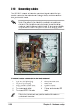
The AP120-E1 chassis includes the power and signal cables that you
need to connect to the motherboard, storage drives, and other devices
that you intend to install.

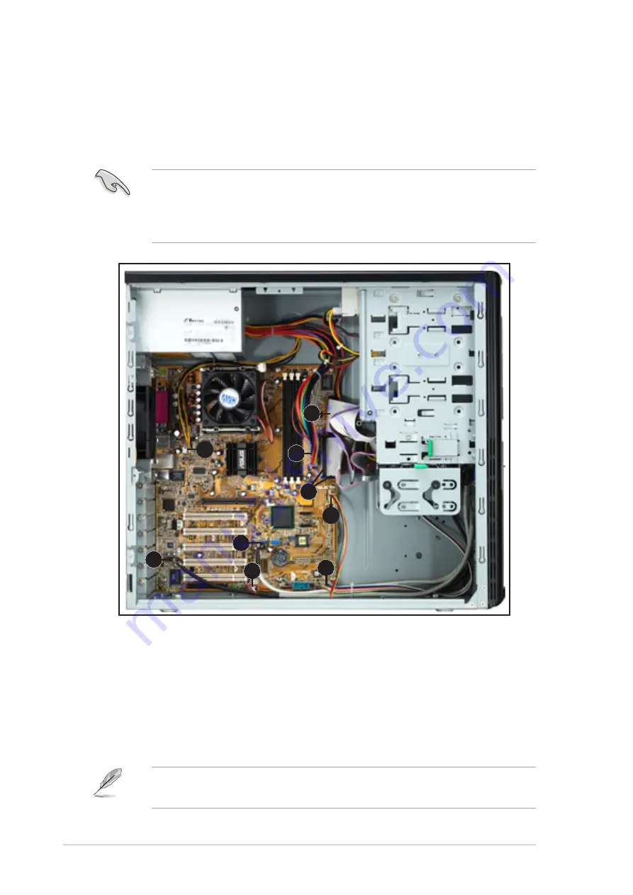
Most of the cables for the chassis kit are already connected upon
shipment. When installing system devices and connecting cables,
make sure that all cables are routed properly for better system stability
and performance. Refer to the picture below when arranging cables.

Refer to the motherboard user guide for detailed information on
motherboard connectors.

1.

4-pin ATX 12V power plug

2.

20-pin ATX power plug

3.

Floppy disk drive ribbon cable

4.

Front panel audio cable

5.

Front panel IEEE 1394 cable

Standard cables connected to the motherboard

6.

Front panel USB cable

7.

Panel cable

8.

System fan cable

9.

Primary and secondary IDE
cable

1

6

2

3

4

5

7

8

9

Summary of Contents for AP120-E1

Page 1: ...P4 Pedestal Server Workstation 800MHz Front Side Bus User Guide AP120 E1 ...

Page 2: ...iness loss of use or data interruption of business and the like even if ASUS has been advised of the possibility of such damages arising from any defect or error in this manual or product Specifications and information contained in this manual ae furnished for informational use only and are subject to change at any time without notice and should not be construed as a commitment by ASUS ASUS assume...

Page 3: ...cessing Unit CPU 2 5 2 4 1 Overview 2 5 2 4 2 CPU installation 2 6 2 5 Installing memory modules 2 8 2 5 1 Memory configurations 2 8 2 5 2 DIMM installation 2 9 2 5 3 Removing a DIMM 2 9 2 6 Installing a hard disk drive 2 10 2 6 1 Qualified hard disk drives 2 10 2 6 2 Hard disk drive installation 2 11 2 7 Installing 5 25 inch drives 2 13 2 7 1 Removing the front panel cover 2 13 2 7 2 Installing a...

Page 4: ...ptions 3 1 Installing optional components 3 2 3 1 1 CPU fan and heatsink assembly 3 2 3 1 2 Second hard disk drive cage 3 4 3 1 3 Expansion card holder 3 7 Appendix A 1 Simple fixes A 2 A 2 Power supply specification A 4 Contents ...

Page 5: ...mful interference to radio or television reception which can be determined by turning the equipment off and on the user is encouraged to try to correct the interference by one or more of the following measures Reorient or relocate the receiving antenna Increase the separation between the equipment and receiver Connect the equipment to an outlet on a circuit different from that to which the receive...

Page 6: ... technician or your dealer Operation Safety Any mechanical operation on this server workstation must be conducted by certified or experienced engineers Before operating the server workstation carefully read all the manuals included with the server workstation package Before using the server workstation make sure all cables are correctly connected and the power cables are not damaged If any damage ...

Page 7: ... if battery is incorrectly replaced Replace only with the same or equivalent type recommended by the manufacturer Dispose of used batteries according to the manufacturer s instructions Electrical hazard do not remove chassis cover This equipment is to be serviced by a trained personnel only Safety information ...

Page 8: ...Hardware setup This chapter lists the hardware setup procedures that you have to perform when installing or removing system components 3 Chapter 3 Installation options This chapter provides information on installing and or removing optional system components 4 Appendix This appendix lists the common problems that you may encounter while using the AP120 E1 server workstation It lists the possible c...

Page 9: ...board user guide This guide contains detailed information on the P4P800S E motherboard 2 ASUS websites The ASUS websites worldwide provide updated information on ASUS hardware and software products See the ASUS contact information on the next page 3 Optional documentation Your product package may include optional documentations such as CD ROM manual warranty flyers and others that may have been ad...

Page 10: ...USA Fax 1 510 608 4555 E mail tmd1 asus com Web site usa asus com Technical Support Telephone General 1 502 995 0883 Notebook 1 510 739 3777 Support fax 1 502 933 8713 Support e mail tsd asus com ASUS COMPUTER GmbH Germany and Austria Address Harkort Str 25 D 40880 Ratingen Germany Telephone 49 2102 95990 Fax 49 2102 959911 Online contact www asuscom de sales Technical Support Telephone 49 2102 95...

Page 11: ...E1 user guide This chapter describes the general features of the server workstation This part also describes the system front and rear panels LED indications and internal components Chapter 1 Product introduction ...

Page 12: ... Optical drive Floppy disk drive Chassis fan 2 AC power cord 3 System screws and labels 4 AP120 E1 support CD including drivers and utilities 5 Documentation ASUS AP120 E1 user guide ASUS P4P800S E user guide 6 Optional items CPU fan and heatsink assembly Second hard disk drive cage with retention base and screws Expansion card holder Contact your dealer immediately if any of the items is damaged ...

Page 13: ...r Supports Intel Prescott processor with 800MHz front side bus LAN Intel CSA 82547E1 1000 Gigabit Ethernet controller Storage 2 x IDE connectors to support 4 UltraDMA100 devices 2 x Serial ATA connectors to support 2 serial ATA HDDs with RAID 0 and RAID1 function Onboard I O PS 2 mouse keyboard port parallel port serial port S PDIF out port floppy disk drive connector 3 x IDE connectors 6 x USB po...

Page 14: ... indicators optical and floppy drives are located on the front panel Flip the front panel I O ports cover to access the front panel USB IEEE 1394 and audio I O ports Front panel I O ports cover Optical drive Floppy disk drive Empty 5 25 inch bays IEEE 1394 port Line Out port Power button and LED HDD LED Reset button USB ports Line In port ...

Page 15: ...for the LED location and the table below for LED description Power connector PCI expansion slots Power suppy unit 9cm chassis fan Line Out port P S2 mouse port S PDIF Out port Microphone port PS 2 keyboard port Parallel port Serial port IEEE 1394 port USB ports AGP expansion slot Wi Fi expansion slot Line In port Gigabit LAN port Voltage selector Side cover locking lever LED Icon Display Descripti...

Page 16: ...CPU socket under the CPU fan 4 DDR DIMM sockets 5 IDE connectors 6 Optical drive 7 Empty 5 25 inch drive bays The CPU fan and heatswink assembly and the hard disk drives are purchased separately 8 9 1 4 5 6 2 3 11 12 14 10 7 13 8 FDD bay 9 Detachable HDD cage 10 Serial ATA connectors 11 ASUS P4P800S E motherboard 12 AGP slot 13 PCI slots 14 Wi Fi slot ...

Page 17: ...ASUS AP120 E1 user guide This chapter lists the hardware setup procedures that you have to perform when installing or removing system components Chapter 2 Hardware setup ...

Page 18: ...it CPU 2 Dual Inline Memory Module s DIMMs 3 Hard disk drive 4 5 25 inch drive s 5 Expansion card s Tool You need a Philips cross screw driver to install some system components 2 2 Removing the side cover To remove the side cover 2 Press the side cover locks outward then pull the side cover toward the rear panel for about one half inch 1 Locate the two side cover locks 1 1 2 ...

Page 19: ...n set aside Viewing the internal structure Without the side cover the internal structure and installed components of the barebone server workstation appear as shown in the following picture Perform the procedures in the succeeding sections to install the CPU system memory disk drives and expansion cards 5 4 ...

Page 20: ...ches 30 5 x 24 5 cm Make sure to unplug the power cord before installing or removing the motherboard Failure to do so may cause you physical injury and may damage motherboard components The motherboard is secured to the chassis by ten screws as indicated by circles in the illustration below Refer to the motherboard user guide for detailed information on the motherboard ...

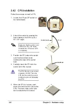
Page 21: ... pin package with 512KB L2 cache The motherboard supports 800 533 400MHz front side bus FSB and allows data transfer rates of up to 6 4GB s Note in the illustration that the CPU has a gold triangular mark on one corner This mark indicates the processor Pin 1 that should match a specific corner of the CPU socket Incorrect installation of the CPU into the socket may bend the pins and severely damage...

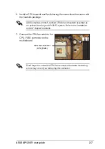
Page 22: ...g the lever sideways then lift it up to a 90 100 angle 3 Position the CPU above the socket such that its marked corner matches the base of the socket lever 4 Carefully insert the CPU into the socket until it fits in place The CPU fits only in one correct orientation DO NOT force the CPU into the socket to prevent bending the pins and damaging the CPU Gold Mark 5 When the CPU is in place push down ...

Page 23: ...e CPU fan connector Hardware monitoring errors may occur if you fail to plug this connector ASUS provides an Intel certified CPU fan and heatsink assembly as an optional item for your AP120 E1 system Refer to the Installation options chapter for details 7 Connect the CPU fan cable to the CPU_FAN1 connector on the motherboard CPU fan connector CPU_FAN1 ...

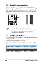
Page 24: ...s list This table lists the memory modules that have been tested and qualified for use with this motherboard P4P800S E P4P800S E 184 Pin DDR DIMM Sockets 80 Pins 104 Pins DIMM3 DIMM2 DIMM1 Obtain DDR DIMMs only from ASUS qualified vendors to ensure system system stability The DDR400 Qualified Vendors List QVL is provided below Visit http www asus com products server RAMsupport htm for the latest Q...

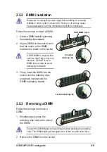
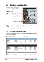
Page 25: ... with extra force 2 Remove the DIMM from the socket 2 5 2 DIMM installation Make sure to unplug the power supply before adding or removing DIMMs or other system components Failure to do so may cause severe damage to both the motherboard and the components Follow these steps to install a DIMM 1 Unlock a DIMM socket by pressing the retaining clips outward 2 Align a DIMM on the socket such that the n...

Page 26: ...fied hard disk drive vendors list Vender Model Interface Speed Capacity Seagate ST380021A IDE 7200rpm 80GB Seagate ST3120023A IDE 7200rpm 120GB IBM Hitachi Deskstart IC35L090AVV207 IDE 7200rpm 80GB Maxtor MAXTOR 6Y80L0 IDE 7200rpm 80GB IBM Hitachi Deskstart IC35L120AVV207 IDE 7200rpm 120GB Maxtor MAXTOR 6Y160L0 IDE 7200rpm 160GB Seagate ST3160023A IDE 7200rpm 160GB IBM Hitachi Deskstart IC35L180AV...

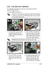
Page 27: ...holes are aligned with the HDD cage screw holes with black rubber stoppers 3 Secure the HDD to the cage with two screws with metal washers on both sides of the cage Configure your hard disk drive as Master Slave device before installing it to the drive cage Refer to the HDD documentation on how to set the drive as a Master Slave device 2 Screw holes 1 4 Re install the HDD cage to the chassis Align...

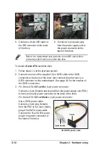
Page 28: ... pin SATA cable to the SATA connector at the back of the drive then connect the other end to a SATA connector on the motherboard See page 3 6 for the location of the SATA connectors 3 For Serial ATA HDDs with a 4 pin power connector Connect a 4 pin female power plug from the power supply unit PSU to the 4 pin male power connector at the back of the drive For Serial ATA HDDs without a 4 pin power c...

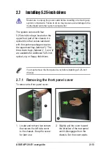
Page 29: ...ves Make sure to unplug the power cable before installing or removing any system components Failure to do so may cause severe damage to the motherboard and other system components 2 7 1 Removing the front panel cover To remove the front panel cover 1 Locate and remove two screws that secure the left side cover to the chassis Keep the screw for later use 2 Slightly pull the cover toward the directi...

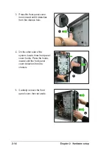
Page 30: ...hook inward until it detaches from the chassis hole 4 On the other side of the system locate three front panel cover hooks Press the hooks inward until the front panel cover detaches from the chassis 5 Carefully remove the front panel cover then set aside 4 5 3 ...

Page 31: ...insert the drive to the bay then push it inward until it is flushed to the chassis front panel 3 Align the optical drive and bay screw holes 4 Secure the drive with two screws on both sides of the bay Screw holes 3 4 2 1 1 Configure your optical drive as Master Slave device before installing it to the drive bay Refer to the optical drive documentation for details To install an additional optical d...

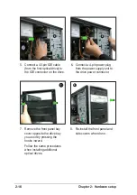
Page 32: ...drive 6 Connect a 4 pin power plug from the power supply unit to the drive power connector 6 5 7 Remove the front panel bay cover opposite the drive bay you used by pressing the hooks inward Follow the same procedures when installing additional optical drives 8 7 8 Re install the front panel and side covers when done ...

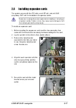
Page 33: ...ore installing or removing an expansion card s Failure to do so may cause severe damage to both the motherboard and the components To install an expansion card 1 Before installing the expansion card read the documentation that came with it and make the necessary hardware settings for the card 2 Lay the system on its side on a flat stable surface 3 Remove the metal bracket opposite the slot that yo...

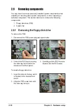
Page 34: ...ystem components when installing or removing other system components or when replacing a defective component This section tells how to remove the following components 1 Floppy disk drive FDD 2 System fan 2 9 1 Removing the floppy disk drive To remove the FDD 1 Disconnect the FDD power plug and signal cable 3 Carefully pull the FDD from the chassis Set the FDD aside 2 Unlock the FDD bay by moving t...

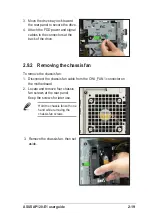
Page 35: ...ack of the drive 3 2 9 2 Removing the chassis fan To remove the chassis fan 1 Disconnect the chassis fan cable from the CHA_FAN1 connector on the motherboard 2 Locate and remove four chassis fan screws at the rear panel Keep the screws for later use Hold the chassis fan with one hand while removing the chassis fan screws 2 3 3 Remove the chassis fan then set aside ...

Page 36: ...cting cables make sure that all cables are routed properly for better system stability and performance Refer to the picture below when arranging cables Refer to the motherboard user guide for detailed information on motherboard connectors 1 4 pin ATX 12V power plug 2 20 pin ATX power plug 3 Floppy disk drive ribbon cable 4 Front panel audio cable 5 Front panel IEEE 1394 cable Standard cables conne...

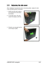
Page 37: ...ide of the chassis 2 Fit the side cover the cover toward the chassis until it fits 3 Slide the cover toward the front until it snaps in place 2 11 Replacing the side cover After installing all components and re connecting cables replace the side cover by following these instructions 3 1 2 ...

Page 38: ...Chapter 2 Hardware setup 2 22 ...

Page 39: ...ASUS AP120 E1 user guide This chapter provides information on optional and removable components you may install to or remove from the system Chapter 3 Installation options ...

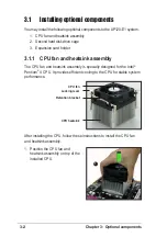
Page 40: ...optional components You may install the following optional components to the AP120 E1 system 1 CPU fan and heatsink assembly 2 Second hard disk drive cage 3 Expansion card holder 3 1 1 CPU fan and heatsink assembly The CPU fan and heatsink assembly is specially designed for the Intel Pentium 4 CPU It provides efficient cooling to the CPU for stable system performance CPU heatsink CPU fan Retention...

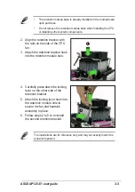
Page 41: ...Do not remove the retention module base when installing the CPU or installing other system components 4 Carefully press down the locking lever on the other side of the retention bracket 5 Attach the locking lever hook into the retention module hole to secure the fan and heatsink assembly in place 6 Follow steps 2 to 5 to re install the second retention bracket 4 5 The illustrations are for referen...

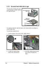
Page 42: ...oks Second hard disk drive cage HDD cage retention base You need to install the retention base to the chassis before installing the second HDD cage To install the retention base 1 Lay the system on its side on a flat stable surface 2 Locate two retention base holes on the chassis floor 3 Insert the retention base hooks to the holes until they fit in place 2 3 ...

Page 43: ...rive 2 Secure the HDD to the cage with two screws with metal washers on both sides of the cage 1 Insert a HDD to the lower bay of the drive cage Make sure that the HDD screw holes are aligned with the drive cage screw holes with black rubber stoppers Screw holes 4 5 1 2 DO NOT install a hard disk drive to the upper bay of the cage ...

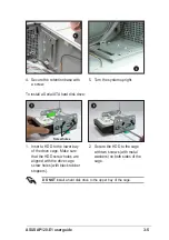
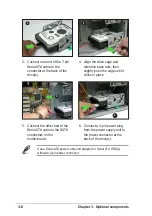
Page 44: ... power supply unit to the power connector at the back of the drive s 5 6 3 Connect one end of the 7 pin Serial ATA cable to the connector at the back of the drive s 4 Align the drive cage and retention base rails then slightly push the cage until it clicks in place 3 4 Use a Serial ATA power cable and adapter for Serial ATA HDD s without a 4 pin power connector ...

Page 45: ... install the retention bracket 1 Lay the system on its side on a flat stable surface 2 Locate two retention bracket screw holes on the chassis floor Install all necessary expansion cards before installing the expansion card holder Assembly Locking screw Adjusting slots Card holders Locking lever Grooves 3 Place the retention bracket over the chassis floor screw holes then secure the bracket with t...

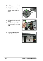
Page 46: ... holder 1 Insert the expansion card holder locking screw to the retention bracket notch as shown 2 Turn the expansion card holder upright 3 Press the locking lever then insert the hooks to the chassis holes 4 Secure the expansion card holder with one screw 1 2 3 4 ...

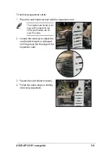
Page 47: ...rd The smaller card holder is for long AGP cards while the other card holders are for long PCI cards 2 Loosen the screw s to adjust the card holder forward or sideward until its groove fits the edge of the expansion card 3 Fasten the card holder screw s 4 Follow the same steps in holding other long expansion 2 3 ...

Page 48: ...Chapter 3 Optional components 3 10 ...

Page 49: ...unter while using the server It lists the possible causes of the problems and offers solutions You may refer to this part and try to solve simple problems before calling customer support The appendix also contains the power supply unit specifications for your reference Appendix Appendix ...

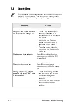
Page 50: ...f the keyboard cable is properly connected to the PS 2 keyboard port The mouse does not work Check if the mouse cable is properly connected to the mouse port The system does not perform power on self tests POST after it was turned on 1 Check the memory modules and make sure you installed the DIMMs the system supports 2 Make sure that the DIMMs are properly installed on the sockets Problem Action S...

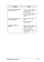
Page 51: ...e sure that the DIMMs are properly installed on the sockets The message Non system disk or disk error appears 1 Check if a bootable HDD is active 2 Check if the HDDs are properly installed Network connection not available 1 Make sure that the network cable is connected to the LAN port on the rear panel 2 Make sure that you have installed the LAN drivers from the support CD ...

Page 52: ...70A max at 115Vac full load cold start at 25 C Efficiency 68 min at nominal input maximum load Output Characteristics Output Load Range Regulation Ripple Voltage Min Max Min Max Max 5V 1 5A 25 0A 5 5 50mVp p 12V 0 2A 8 0A 5 5 120mVp p 12V 0A 0 8A 10 10 150mVp p 5V 0A 0 5A 5 5 100mVp p 5Vsb 0A 2 0A 5 5 100mVp p 3V3 0A 14 0A 5 5 50mVp p Over Voltage Protection OVP Output Voltage Maximum Voltage 5V 6...

Reviews: