


ASUS A7VI-VM User’s Manual
33
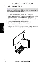
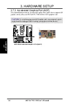
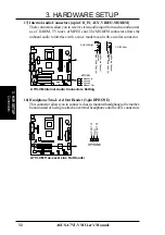
3. HARDWARE SETUP
Connectors
3. H/W SETUP
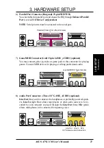
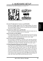
19) USB Header (10-1 pin USB2)
If the USB port connectors on the back panel are inadequate, this USB header is
available for two additional USB port connectors. Connect the USB headers to
the 2-port USB connector set and mount the bracket to an open slot on your
chassis.
A7VI-VM
®
A7VI-VM USB Port
USB Power
USBP2
–
USBP2+
GND
NC
USB Power
USBP3
–
USBP3+
GND
1
5
6
10
USB2
20) SMBus Connector (5-1 pin SMB)
This connector allows you to connect SMBus (System Management Bus) de-
vices. SMBus devices communicate by means of the SMBus with an SMBus
host and/or other SMBus devices. SMBus is a specific implementation of an I
2
C
bus, which is a multi-device bus; that is, multiple chips can be connected to the
same bus and each one can act as a master by initiating data transfer.
SMBCLK
Ground
SMBDA
T
A
+5V
1
A7VI-VM
®
A7VI-VM SMBus Connector
SMB
Summary of Contents for A7VI-VM
Page 1: ... A7VI VM JumperFree PC133 VC133 200 MHz FSB AGP 4X Socket A Motherboard USER S MANUAL ...
Page 74: ...ASUS A7VI VM User s Manual 74 4 BIOS SETUP 4 BIOS SETUP This page intentionally left blank ...
Page 91: ...This product may not be available in certain areas Ask your dealer for availability ...


