ASTRO SR-8450 Instruction Manual Download Page 23

Chapter 4 Operation from the remote controller 

23 

Chapter 4  Operation from the remote controller 

The main operation of this device is performed by the remote controller.   
  

4.1 

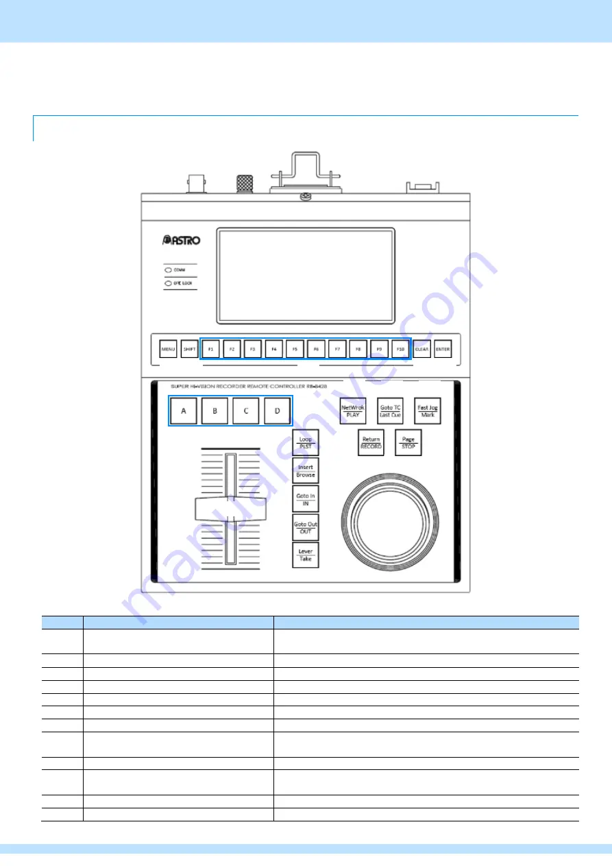
Name and function of each part of the remote controller 


number 

name 

explanation 


COMM LED

  / 

OPELOCK LED


Notifies you of the establishment of communication with the main unit. 
/Notifies you of the operation prohibited state. 


LCD


Various displays are performed. 


MENU

Button 

Transition to the MENU screen. 


SHIFT

Button 

Switch between Primary MENU and Secondary MENU.   


FUNCTION

Button 

Select clip numbers, etc. and select MENU items. 


CLEAR

Button 

Delete clips, etc. and move the hierarchy of MENU. 


ENTER

Button 

Create clips, etc. and decide on MENU items. 


A

Button  / 

B

Button  / 

C

Button  / 

D

Button 

Switch the output camera input system in Live mode. 


Loop/PLST

Button 

Transition to Playlist editing screen and transition to Loop mode. 


Insert/Browse

button 

Perform transition operations between clips in Playlist and insert clips into 
playlists. 


Goto In/IN

Button 

Set the IN point of the clip and move the clip to the IN point of the clip. 


Goto Out/OUT

Button 

Set the OUT point of the clip and move the clip to the OUT point.   


Summary of Contents for SR-8450

Page 1: ...8K Video Server SR 8450 Instruction Manual Ver 1 20 ASTRODESIGN Inc...

Page 2: ...If thunder is heard during outdoor use immediately turn the power off unplug the power cord from the power outlet and move the unit to a safe place Failure to do so may result in fire and electric sh...

Page 3: ...crystals may leak from the panel Keep the liquid away from your mouth and skin and do not inhale the vapors If any liquid should contact your mouth or eyes wash away immediately with water Furthermore...

Page 4: ...Safety precautions Always observe 4 If the Unit Malfunctions or Trouble Occurs Stop using the unit immediately unplug the power cord and contact your dealer or an ASTRODESIGN Inc sales representative...

Page 5: ...te Controller RB 8428 main unit 1 AC power cord 1 7A BNC cable for remote controller 1 1 3m 1 If you would like to request BNC cables for remote controller of different lengths please contact the Busi...

Page 6: ...Screen FAN Status 20 3 2 MENU Screen 21 3 2 1 Maintenance drawing 21 3 3 SSD Information Screen 22 3 4 Thumbnail screen 22 Chapter 4 Operation from the remote controller 23 4 1 Name and function of ea...

Page 7: ...otected clips and playlists 53 4 8 MENU 57 Chapter 5 When you are in trouble 60 5 1 If it doesn t work properly 60 5 2 When an abnormality or malfunction occurs 60 Chapter 6 Device Specifications 61 6...

Page 8: ...neously 4 input modes Up to 4 hours of continuous loop recording is possible per input system 2 input modes Up to 8 hours of continuous loop recording is possible per input system You can create edit...

Page 9: ...Chapter 1 About this device 9 1 3 Names and functions of each part The names and functional overviews of each part of this device are as follows 1 3 1 This device SR 8450 front view OPEN OPEN...

Page 10: ...oad the SSD SD card slot Insert the SD card upgrade the firmware version and obtain log information Used only during maintenance STANDBY Switch Start or Shut off this device Main power switch Turn on...

Page 11: ...mote controller The left side controls 8K 12G SDI OUT1 output system 1 and the right side controls 8K 12G SDI OUT2 output system 2 The Baud Rate is 4 000 000 bps 10GbE Ethernet 1 Communicate with exte...

Page 12: ...ea For details see Chapter 4 Operation from Remote Controller number name explanation Remote Controller Power Switch Start or shut off the remote controller AC Inlet Connect the supplied AC cable REMO...

Page 13: ...ST 2082 12 8K YCBCR 4 2 2 59 94p 10bit 2sample interleave Video signal corresponding to the above specifications 12G SDI SMPTE ST 2082 12 8K YCBCR 4 2 2 59 94p 10bit 2sample interleave Video signal c...

Page 14: ...ADI signal output B remote controller RB 8428 External TIMECODE exert oneself External MADI signal output A External TIMECODE input Peripherals MADI input External MADI signal output C External refere...

Page 15: ...HD SDI SMPTE 292M 1920x1080 59 94i Input of peripheral devices corresponding to the above specifications 12G SDI SMPTE ST 2082 12 8K YCBCR 4 2 2 59 94p 10bit Input of peripheral devices corresponding...

Page 16: ...ars followed by the HOME screen 2 1 5 Shutting off the device 1 By operation with the remote controller stop recording and playback completely 2 Press and hold the STANDBY switch for 3 seconds and the...

Page 17: ...to connect start and shut off the remote controller 1 Make sure the remote controller power switch is turned OFF 2 Connect the BNC cable for the remote controller to the REMOTE terminal 3 Connect the...

Page 18: ...area on the SSD The percentage decreases according to the clip length registered on the SSD When no clips are registered 100 is displayed SSD Information Displays the SSD Information screen For detai...

Page 19: ...to move to 3 1 4 HOME Screen FAN Status Press the status display toggle switch on the left side to enter 3 1 2 HOME Screen Temperature Status 1 name explanation POWER Status Displays the status of the...

Page 20: ...the right to move to 3 1 1 HOME Screen SDI IN Status Press the status display toggle switch on the left side to enter 3 1 3 HOME Screen Temperature Status 2 name explanation FAN Status Displays the st...

Page 21: ...ation HOME Go to the HOME screen Maintenance Set the RTC and collect logs to the SD card For details see 3 2 1 Maintenance Screen Information Display version information and perform version upgrade Fa...

Page 22: ...een On the thumbnail screen LINE OUT is displayed Touch the LCD on the thumbnail screen to return to the HOME screen number name explanation HOME Go to the HOME screen SSD Remain Displays the remainin...

Page 23: ...Switch between Primary MENU and Secondary MENU FUNCTION Button Select clip numbers etc and select MENU items CLEAR Button Delete clips etc and move the hierarchy of MENU ENTER Button Create clips etc...

Page 24: ...ays back clips etc and references clips recorded on other devices on the 10GbE network for future support Return RECORD button Start continuous recording Goto TC Last Cue button For future support Pag...

Page 25: ...rn RECORD button and LIVE mode and start continuous loop recording The Return RECORD button lights up red 4 2 2 PlayBack mode Press the Network PLAY button or when you operate T bar it enters PlayBack...

Page 26: ...position and playback speed is shown in the figure below 1 Constant speed playback At the top of T bar the video recorded at 60p will be played back at constant speed 60p 3 Stop At the bottom of T ba...

Page 27: ...on to increase the number of frame feed steps The Fast Jog Mark button will light up green 4 2 4 Full end of recording 1 Press the Return RECORD button and the Page STOP button at the same time 2 Pres...

Page 28: ...e most recently referenced Mark point press the Goto TC Last Cue button 4 4 Operations about Goto TC During simultaneous recording playback it is possible to Cue up to any timecode 1 During LIVE PlayB...

Page 29: ...This article describes the following four operations about clips Register a clip Play a clip Edit the IN OUT point of a clip Erase clips The clip along with Page and BANK is organized as follows foll...

Page 30: ...n in the order of SHIFT button Page STOP button select Page by pressing any one from the F1 F9 button The detailed LED lighting pattern is as follows Currently BANK 1 on Page1 is specified and the F1...

Page 31: ...g pattern is as follows Currently BANK1 of Page9 is designated and F2 F3 F5 F6 F8 F9 buttons light up green Press the SHIFT button The buttons indicating BANK 1 3 and 8 in which the clip is registered...

Page 32: ...d clip numbers as in the example shown in 4 5 1 Suppose you register clip 6 in BANK8 of Page 9 1 Follow the instructions in 4 5 1 and specify Page BANK 2 Press the Goto In IN button at any frame to se...

Page 33: ...e remote controller 33 4 Press the button that does not light up green on the F1 F10 button to register the clip to the corresponding clip number As an example if you newly register clip 6 here the F6...

Page 34: ...hts up red As an example clip 7 is played here the F7 button will light up red 3 The selected clip is played by pressing the NetWork PLAY button or moving T Bar The NetWork PLAY button will light up g...

Page 35: ...ong the F1 F10 buttons the button that has already registered the clip lights up green so press the button corresponding to the clip number you want to copy or move from among these Among the F1 F10 b...

Page 36: ...press the ENTER button the corresponding BANK is deleted CLEAR button to cancel it Among the F1 F10 buttons the button corresponding to the selected BANK number is turned off 4 5 8 Delete clips in Pag...

Page 37: ...t To play a playlist follow these steps 1 Follow the instructions in 4 5 1 to specify Page followed by BANK10 2 Among the F1 F10 buttons the button that has already created a playlist lights up green...

Page 38: ...ps you want to add to the currently selected playlist are stored 4 If you press the ENTER button after pressing the button corresponding to the clip number you want to add to the currently selected pl...

Page 39: ...ss the Goto In IN button to set a new IN point and press the Goto Out OUT button to set a new IN point Set the OUT point 4 6 7 Edit the playback speed of clips in a playlist To edit the playback speed...

Page 40: ...ack and the next clip gradually enters normal playback from the specified solid color In Fade To From Color Do Fade To Color and Fade From Color Specified solid color To set the Transition Type of a c...

Page 41: ...ress the ENTER button to complete the setting Press the CLEAR button to cancel it The maximum setting time is 20 seconds It does not apply if the Transition Type is Cut If the setting value of Transit...

Page 42: ...nd select R G B and adjust the Transition Color by operating Jog 7 Press the ENTER button to complete the setting Press the CLEAR button to cancel it Each color can be set in the range of 0 255 A colo...

Page 43: ...protected clip playlist is eligible for deletion display the following pop up on the LCD for 3 seconds This clip is protected and can t be cleared if the clip is eligible for CLEAR Some clips are prot...

Page 44: ...e Page BANK and clip numbers as in the example shown in 4 5 1 Protect operations are performed in BANK8 of Page 9 1 Follow the instructions in 4 5 1 and specify Page BANK 2 Press the F1 F10 button tha...

Page 45: ...g clip number is protected As an example when protecting a new clip 9 a pop up with the following image will appear on the LCD for 2 seconds 4 To unprotect a clip press the F1 F10 button that lights u...

Page 46: ...ler 46 5 If the clip you want to unprotect is included in a protected playlist the following pop up warning appears As an example if clip 1 is included in a protected playlist a pop up with the image...

Page 47: ...d with the same Page BANK and clip numbers as in the example shown in 4 5 1 Protect operation is performed in Page9 1 Follow the steps in 4 5 1 to move to the BANK selection tier 2 Press the F1 F10 bu...

Page 48: ...mber is protected As an example when protecting a new BANK1 a pop up with the following image will be displayed on the LCD for 2 seconds 4 To remove the protection of BANK press the F1 F10 button that...

Page 49: ...BANK that tries to unprotect all at once has clips included in the protected playlist the following pop up warning will be displayed As an example if clip 1 is included in a protected playlist a pop u...

Page 50: ...clip is registered with the same Page BANK and clip numbers as in the example shown in 4 5 1 1 Follow the steps in 4 5 1 to transition to the Page selection hierarchy 2 Press the F1 F10 button that l...

Page 51: ...mber is protected As an example when protecting Page1 anew a pop up with the following image will be displayed on the LCD for 2 seconds 4 To remove the protection of Page press the F1 F10 button that...

Page 52: ...age that tries to unprotect all at once has clips registered in a protected playlist the following pop up warning will be displayed As an example if clip 1 is included in a protected playlist a pop up...

Page 53: ...e performed clip 6 in BANK 3 in Page 9 was protected BANK 8 in Page 9 was protected Page1 was protected After the operation of not a single additional clip has been registered 1 Press the SHIFT button...

Page 54: ...w the steps in to move to the BANK selection tier As an example because BANK 8 of Page 9 is protected the F8 button lights up yellow After this if a new clip is registered in BANK 8 of Page 9 the F8 b...

Page 55: ...he steps in 4 5 1 to transition to the Page selection hierarchy As an example because Page1 is protected the F1 button lights yellow After this if you register a new clip in BANK of Page 1 the F1 butt...

Page 56: ...and protected The F1 F10 button lights up green The caution message is also cleared from the LCD While transitioning to Protect Confirmation Mode Other than the operations described in Operation 4 7 1...

Page 57: ...2 0 562 Adjust the vertical phase F5 Audio In Out F1 Audio In F1 MADI IN F2 SDI Embedded Audio Records the audio input from MADI IN Records audio multiplexed in the SDI input F2 4K Out CH Assign 1 F1...

Page 58: ...the settings to memory Calls the setting value from memory F8 Factory Default ENTER OK CLEAR Cancel Restore all settings to factory defaults F3 Guard Time F1 F10 ss up to 30 seconds Initial value 30...

Page 59: ...Press to reflect the audio assignment CLEAR to cancel it The initial values for audio assignments for each SDI OUT are as follows SDI OUT Audio CH 1 2 3 4 5 6 7 8 9 10 11 12 13 14 15 16 4K Audio Assi...

Page 60: ...IGN Inc This device SR 8450 symptoms cope The output video is distorted On the HOME screen of the touch panel LCD check that the SDI status is set to Locked Remote Controller RB 8428 symptoms cope but...

Page 61: ...nput HD3 value BB signal 75 BNC passive through the clock Auto termination not supported MADI I O 75 BNC 4 inputs and 2 outputs TIMECODE I O BNC LTC 1 input 2 outputs REMOTE BNC connector 75 2 ports S...

Page 62: ...Chapter 6 Device Specifications 62 6 1 2 appearance...

Page 63: ...nce item specification REMOTE BNC connector 75 Remote control terminal General Specifications Power supply voltage AC100V 240V Operating temperature range 0 40 Operating humidity range 20 80 RH non co...

Page 64: ...perations on GotoTC points 36 4 5 7 Erase and add BANK based clips playlists 4 5 8 PAdd erase clips per AGE 39 4 6 7 Add editing the playback speed of clips in a playlist 40 4 6 8 Add Transition Type...

Page 65: ...roduced without permission The information in this document is subject to change without notice for improvement Please note that we are not responsible for the impact of incorrect use results For inqu...

Reviews: