ASTRO-PHYSICS Mach1GTO Manual Download Page 22

SERVO MOTOR DRIVE 

The Servo Motor Drive system on the 

Mach1GTO

 uses the same motors, the same GTOCP3 control box and the same keypad 

as its bigger siblings, the 900GTO and 1200GTO.  The gear train is just as heavy-duty, and the worm gears are massive and 
incredibly precise.  This is an extremely robust system for a mount of this size, but since the focus of the 

Mach1GTO

’s design 

was on the serious observer and imager, we felt that it was well worth it. 

Another innovative feature of the Mach1GTO is that the declination and right ascension servo motor gearboxes are 
interchangeable.  In the extremely rare chance that your RA drive would fail in the field (at a star party in the middle of nowhere 
under perfect skies according to Murphy’s Law), you can simply swap the two drive boxes and still have the mount’s tracking 
ability.  Please note that while the declination servo drive box is on the RA axis, you may have a little more periodic error than 
you are used to, since the fine tuning was done on the RA’s original servo drive.   Also, since you will be using a different worm 
gear, your PEM will be different.  For imaging, you may need to retrain your PEM.  For visual observing, simply turn PEM off 
while using the declination servo drive box on the RA axis. 

To remove a servo drive box, first separate the two axes, and then remove the four small screws on the servo drive box that hold 
the cover with the servo cable connector, and pull the cover off to the side.  Its wires will remain attached to the motor.  Next, 
carefully unscrew the two shoulder bolts that hold the servo drive box to the axis.  Note that there is a spring exerting pressure 
against these two shoulder bolts, and take note of the spring’s position against the shoulder bolts.  When they come loose, the 
spring will push them over.  That is fine; don’t try to completely remove the bolts.  The servo drive box will now separate from the 
axis.  To re-install a servo drive box, carefully set the box into position making sure that the worm gear settles into the teeth of 
the worm wheel.  Put the two shoulder bolts in place, but only snug down at this point.  Make sure that the spring is properly 
positioned below the ridge in each shoulder bolt.  Gently rock the servo drive box back and forth, and then center the box in its 
range of motion.  Now fully tighten the shoulder bolts.  Finally, replace the cover with the four screws and you’re ready to go.   

As more detailed information from real life experience becomes available, it will be posted in the Technical Support Section of 
our website. 

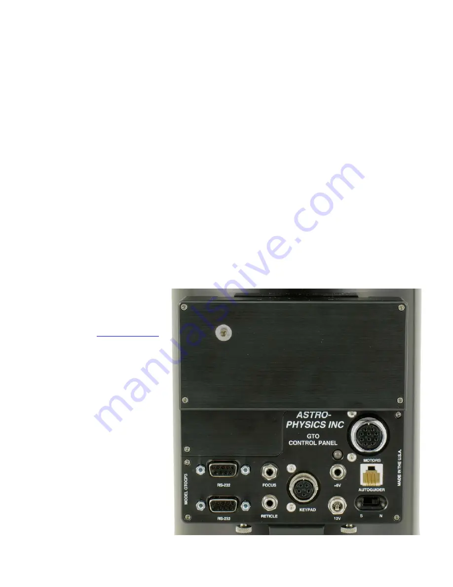
GTO Control Box – GTOCP3 

The GTO control box contains all of the circuitry to drive the two servo motors and the logic required to navigate the sky. It 
will be operational and track at the sidereal rate when connected to both motors of the mount and a power source.  In order 
to control the movement of the mount, you will need to connect at least one of these:  

 GTO 

Keypad. 


Computer with PulseGuide by 
Sirius Imaging. The CD for this 
program is included with the 
mount. For the most updated 
version of the software, check out 
the website 

www.pulseguide.com

.  


Computer with astronomical 
software such as 

DigitalSky Voice


or planetarium programs such as 
Software Bisque’s 

TheSky™,  

Imaginova’s

  Starry Night™,  

Nova Astronomics

’ The Earth-

Centered Universe (ECU

) version 

3.1 or later, and Chris Marriot’s


Sky Map Pro 6 

or any ASCOM 

compatible telescope software (all 
purchased separately). 

The 

Mach1GTO

’s  GTO Servo Control 

Box comes with a Control Box Adapter 
for direct mounting on your pier or 
tripod as well as handy pouch for 
hanging from a knob on the base of 
your 

Mach1GTO

 mount. Please 

remember that this box contains 
advanced electronics and must be 
treated with the same care given to 
other fine equipment. You can see that 
the unit is built to be rugged, however 
it is not indestructible.   

21 

Summary of Contents for Mach1GTO

Page 1: ......

Page 2: ...Plate 12 Assemble Counterweight Shaft 13 Optional 10 7 x 1 875 Counterweight Shaft 14 Attach Mounting Rings purchased separately 14 Fine Polar Alignment 14 Methods for fine polar alignment 15 Altitud...

Page 3: ...are 24 Cleaning and Touch up 25 Mount Maintenance 25 ADDITIONAL TIPS AND SUPPORT 25 TROUBLESHOOTING 25 RECOMMENDED READING FROM OUR STAFF 28 CHARACTERIZING THE DEC AXIS MOTIONS 29 ASTRO PHYSICS MOUNTI...

Page 4: ...aft M1053 and Safety Stop M12676 for use with 5 lb 5SCWT 10 lb 10SCWT and 18 lb 18SCWT counterweights Handy for travel or if you already own a 900 or 1200 series mount Polar Alignment Scope with Illum...

Page 5: ...e weights as 900 and 1200 series mounts Latitude range 0 to 70 degrees with or without polar scope attached Azimuth adjustment Approximately 25 degrees 12 5 deg from center Motors Zero cogging servo m...

Page 6: ...lete remote control of all Astro Physics GTO mounts It derives its name from its most distinctive feature pulse guiding which can improve unguided tracking Specifically it can help correct tracking er...

Page 7: ...and handling Please refer to the following illustrations The parts are labeled so that we can establish common terminology Throughout the text SMALLCAPS are used to refer to parts that are illustrated...

Page 8: ...the COUNTERWEIGHT ADAPTER down and the DECLINATION HUB PLATE up as in the Assembly Diagram Unlike the bigger 900GTO and 1200GTO mounts the dec axis of the Mach1GTO must be straight and square to the R...

Page 9: ...g Pier are included with the pier Please refer to those instructions for assembly adjustment and leveling procedures Your Mach1GTO will fit into the 6 Eagle Adjustable Folding Pier without any additio...

Page 10: ...alignment without having the pier level but it is more difficult With a pier that is not level each adjustment in azimuth also causes a minor shift in altitude and vice versa This is why we have inclu...

Page 11: ...alignment just snug down the AZIMUTH LOCK KNOBS One full turn of the AZIMUTH ADJUSTER KNOB is approximately 1 37 degrees 82 arc minutes 4 Altitude latitude adjustments The altitude adjustment mechani...

Page 12: ...ich may be sufficient for casual visual observations if you are not planning to slew to target objects with the keypad When the R A motor is engaged the power is plugged in it will compensate for the...

Page 13: ...h a large plate it may be too large for this mount 15 RIBBED MOUNTING PLATE 900RP The finished plate is 0 75 thick 15 long and 6 5 at its widest point The width of the plate tapers to 4 75 A pair of k...

Page 14: ...late down The remaining two can then still hold the DECLINATION HUB PLATE in place on the DECLINATION AXIS HUB while the mounting plate is being attached The four remaining holes are more than adequat...

Page 15: ...ad luggage compartment but you still have to be able to lift it up that high You must also be aware of all rules and regulations regarding weight limits and allowable case sizes not to mention potenti...

Page 16: ...e To use one of these earlier polar scopes screw the unit into the adapter and then back it off to align Polaris relative position to the pole Proceed normally turning the polar scope wherever the ins...

Page 17: ...h clutch knob has a 3 16 hex socket for tightening with an Allen key Using the provided hex key you can lock up the clutches so that only the worm drives are able to move each axis You should NOT atte...

Page 18: ...cially vulnerable when a German Equatorial Mount was swapping sides to point at the other side of the meridian The problem was that all these wires going to all these different locations had to deal w...

Page 19: ...reach in the bottom of the RA axis to help you guide the cable end out the access hole When all the necessary cables have been run through the mount turn the RA axis so that the mount is in its normal...

Page 20: ...in place But what about polar alignment if the cables have been run out the bottom of the RA axis or if there are very many cables Simple Set your mount up on its tripod or pier but don t tie off or...

Page 21: ...weight of the cables doesn t cause movement flexure in the imaging system over a long exposure Please feel free to contribute hints and tricks of your own for future editions of this manual At Astro P...

Page 22: ...try to completely remove the bolts The servo drive box will now separate from the axis To re install a servo drive box carefully set the box into position making sure that the worm gear settles into...

Page 23: ...g then turn RS 232 Connectors These serial port connections are used to connect your mount to your PC computer You must provide your own straight through non crossing cables with a 9 pin DB9 male conn...

Page 24: ...purchased separately or as part of a CCD Imaging Camera or Autoguider The autoguider will be functional and ready to go as soon as you plug it in Please refer to the appropriate manual from the manuf...

Page 25: ...e added This combination is ideal for low wear since the damping grease portion allows the grease to stay on the teeth and not get wiped off by the motion of the worm Although this combination works w...

Page 26: ...oblem but it is still a good idea to periodically once or twice a year inspect and if necessary re tighten any easily accessible fasteners Additional maintenance information can be found below in the...

Page 27: ...y because of the higher gain with this much voltage The system works very well with 15 16 volts The Mach1GTO should work very smoothly at 12 volts For polar alignment I am using declination drift tech...

Page 28: ...chine oil to the center posts of the individual gears Just remove the cover on the gearbox and add the oil drops The noise is nothing to worry about Refer to the section of this manual entitled Slewin...

Page 29: ...n regarding the principles of mount construction and operation using setting circles eyepiece projection etc Illustrations and formulas galore Many of the instruments pictured are outdated however the...

Page 30: ...CHARACTERIZING THE DEC AXIS MOTIONS 29...

Page 31: ...4 20x5 8 Socket Head Cap Screw 4 20x5 8 Flat Socket Ca Screw 1 20x5 8 Flat Socket Cap Screw 2 20x1 Socke Head Cap Screw 6 20x1 Flat Socket Cap Screw and 6 20x5 8 Flat Socket Cap Screw Use Q4047 Adapt...

Reviews: