Start-up, shut-down & manual bypass
4
OM226132 Rev. A
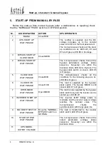
5. START-UP FROM MANUAL BY-PASS
Before the start-up from manual by-pass (after a maintenance or repairing) check
that the “NORMAL-BYPASS” switch is in
BYPASS
position.
Nr.
LCD DISPLAYING
ACTION
UPS OPERATION
1
BLANK
Close RCB
2
UPS START UP
WAIT PLEASE
The rectifier is supplied and the DC
voltage increases up to the nominal
value. All LED’s in the front panel are lit.
The microprocessor checks all the start-
up conditions are ok. LED’s #1, #3 and
#7 are lit green. LED #8 is lit orange.
3 BYPASS
STARTUP
CLOSE SBCB
Close SBCB
4 BYPASS
STARTUP
WAIT PLEASE
The microprocessor checks that all the
by-pass parameters (voltage, phase
sequence, frequency) are within the
tolerance limits. LED #2 is lit green. The
by-pass static switch is closed, LED #6
is lit orange.
5 CLOSE
BCB
WAIT PLEASE
Close BCB
The microprocessor checks all the
conditions for the following step are ok.
LED #4 is lit green.
6 CLOSE
OCB
WAIT PLEASE
Close OCB
The load is supplied by the by-pass
static switch. The breaker MBCB is still
closed. LED #7 is lit green.
7 OPEN
MBCB
WAIT PLEASE
Open MBCB
The load is now supplied by the by-pass
static switch only and the inverter can be
started-up. LED #8 off.
8
INVERTER START UP
WAIT PLEASE
The inverter IGBT bridge starts to
modulate and the inverter output voltage
reaches the nominal value. The
microprocessor checks the
synchronisation with the by-pass line.
9
MOVE BYP SWITCH
WAIT PLEASE
Move the “NORMAL-
BYPASS” switch on
NORMAL
The load is transferred to the inverter
static switch. LED #5 is lit green.
10
START UP END
WAIT PLEASE
The microprocessor checks that all the
output parameters (voltage, phase
sequence, frequency) are within the
tolerance limits.
11 UPS
MODEL
OUTPUT VOLTAGE

