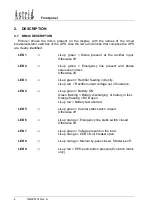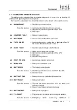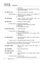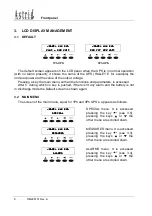
Front panel
OM226131 Rev. A
9
3.3 MEASURES
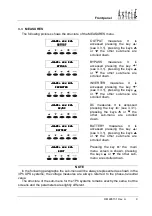
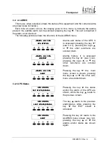
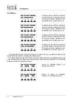
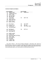
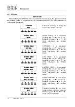
The following pictures shows the structure of the MEASURES menu.
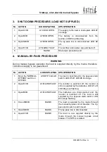
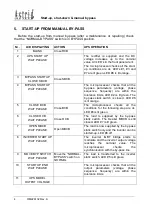
<NAME> xxx KVA
<NAME> xxx KVA
<NAME> xxx KVA
<NAME> xxx KVA
OUTPUT
OUTPUT
OUTPUT
OUTPUT
OUTPUT measures. It is
accessed pressing the key
(see 3.3.1), pressing the keys
or
the other sub-menu are
scrolled down.
<NAME> xxx KVA
<NAME> xxx KVA
<NAME> xxx KVA
<NAME> xxx KVA
BYPASS
BYPASS
BYPASS
BYPASS
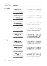
BYPASS measures. It is
accessed pressing the key
(see 3.3.1), pressing the keys
or
the other sub-menu are
scrolled down.
<NAME> xx
<NAME> xx
<NAME> xx
<NAME> xxx KVA
x KVA
x KVA
x KVA
INVERTER
INVERTER
INVERTER
INVERTER
INVERTER measures. It is
accessed pressing the key
(see 3.3.1), pressing the keys
or
the other sub-menu are
scrolled down.
<NAME> xxx KVA
<NAME> xxx KVA
<NAME> xxx KVA
<NAME> xxx KVA
AC/DC
AC/DC
AC/DC
AC/DC
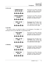
DC measures. It is accessed
pressing the key
(see 3.3.1),
pressing the keys or the
other sub-menu are scrolled
down.
<NAME> xxx KVA
<NAME> xxx KVA
<NAME> xxx KVA
<NAME> xxx KVA
BATTERY
BATTERY
BATTERY
BATTERY
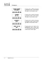
BATTERY measures. It is
accessed pressing the key
(see 3.3.1), pressing the keys
or
the other sub-menu are
scrolled down.
<NAME> xxx KVA
<NAME> xxx KVA
<NAME> xxx KVA
<NAME> xxx KVA
EXIT
EXIT
EXIT
EXIT
Pressing the key
the main
menu screen is shown, pressing
the keys or the other sub-
menu are scrolled down.
NOTE
In the following paragraphs the sub-menu will be always represented as shown in the
3Ph UPS systems; the voltage measures are always referred to the phase-to-neutral
value.
The structure of the sub-menu for the 1Ph systems remains exactly the same, but the
screens and the parameters are slightly different.

