12
HEATING BOILERS
: Astra G-18 E, Astra G-25 E, Astra G-32 E, Astra G- 40 E
• connection of the
cIRcUlaTIon PUMP
In order to insure a continuous flow of
water, a circulation pump is to be installed
in the system, on the return water pipe
behind the mixing valve. The electronic
controller of the boiler controls the
pump. Before connecting the circulation
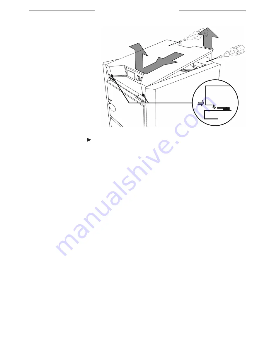
pump, remove the rooftop cover of the
boiler (Fig. 7). The cover is removed in
the following sequence: 1) unscrew two
fastening bolts, 2) lift the backside part
of the cover, 3) push the cover forward
and then lift it up. Connect the wire of
the circulation pump to the 12-way
electric terminal connector, contacts No
11 and 12, marked with the sign (See
Fig. 6 “Circuit diagram of the boiler”). Connect the earthing wire of the pump to the contact No. 1 on the same connector.
• connection of the Ventilator
The boiler is transported with the ventilator removed and put into the upper chamber of the boiler (Astra G-18E, Astra
G-25E, Astra G-32E) or fastened using adhesive tape to the top of the packaging frame of the boiler (Astra G-40E).
For boilers Astra G-18E, Astra G-25E, Astra G-32E: unpack the ventilator and release the clamp on the nipple at the ventilator
installation bed 10 (Fig. 1). Put the opening of the ventilator onto the nipple, slip a clamp on top and tighten it. Check if a ventilator
case sits tightly. Connect the wires of the ventilator cable lead through a hole in the rooftop cover of the boiler to the terminals of
the ventilator. For boilers Astra G-40E: unpack the ventilator, screw its case on at the ventilator installation bed 10 (Fig. 1) using
the existing bolts and check the stiffness of the connection. The ventilator cable has already been connected during fabrication.
• controllinG the temPerature of water returninG to the Boiler
It is absolutely necessary to maintain the temperature of the water returning from the heating system to the boiler at a
constant level, no less than 65°C, as this will prolong the lifetime of the boiler and will make the combustion process more
effective. This is because when a constant high temperature of water returning to the boiler is maintained, there arises
significantly less water vapour condensation inside the boiler. The heavy water condensation is harmful to the boiler, because
deposits of tar, pitch and soot accumulate on the walls of the heat exchanger, causing intense metal corrosion. Moreover, the
resulting layer of soot impedes effective heat transfer and the efficiency of the boiler falls.
In order to maintain the temperature, we recommend installing the small circulation circle together with a Swedish-made
thermoregulation device, “Laddomat 21-60”. Make sure that the “Laddomat” is supplied with the 78°C or 72°C thermostat
cartridge. The mentioned temperature is the one at which the valve of the device opens completely. However, the actual
temperature of the water returning from the system and getting into the boiler after mixing, is 5-6°C lower. The higher the
temperature of the return water is, the better it is for the boiler. Thermoregulation devices of other manufacturers could be
used for maintaining the temperature of the returning water as well.
• heatinG outPut, water temPerature anD water flow relationshiP
The heating output supplied to a heating system depends directly upon the difference of flow and return water temperatures
fig. 7 Removing the rooftop cover of the boiler
1. Unscrew bolts; 2. Lift the backside of the cover; 3. Push the cover forward , then raise.
3
1
1
2


