background image


PN# 500-16900


Page 11 

Rev. D, 12/11 

program additional User codes, you follow the procedures described above for setting the User 
code in memory location 01 but you employ memory locations 02 through 59.  For example, 
once the unit is in program mode (rapid yellow flash), entering 0-2 followed by a code sequence 

will enter a second User code.  The same is true when you enter prefixes 0-3, 0-4 up to 5-9.  
When you’re programming multiple User codes, note that you can enter them one right after 
another.  When a code is accepted, the unit signals by two red flashes.  It then automatically 
goes back into program mode and another code can be immediately entered without exiting 
program mode.  Be sure to test all the codes you have entered before you consider 

programming complete.  You can individually erase any code (including the Program code) by 
entering program mode, pressing the prefix for the code (01-59) and then pressing the Bell key 
or waiting 5 seconds until you get the two red flashes
 
4.3  “MASTERKEY” USE OF THE HARD CODE 
The primary use for the Hard code is to allow simple single code “fixed” operation as is described 

in Section 4.1.  The Hard code can only be set or changed from the “Hard Code” button in the 
CPU board.  It is deliberately kept separate from all programming functions.  Another use for it, 
however, is as a “masterkey” code.  For example, consider a facility with multiple DK-26’s under 
the control of different departments.  Each department might want to employ different Program 
and User codes to restrict cross access but a common Hard code could be established for all of 

the units so that security management personnel could enjoy universal access.  This Hard code 
will never be lost from keypad operations (the CPU board has to be accessed). 
 
4.4  SUBSET CODES 
When you recognize that the DK-26 accepts multiple codes of different lengths, it is possible 

that one code will be a subset of another.  For example, suppose you programmed “1-3-3-5-8” 
and then programmed “3-3-5” as another code.  When you try to enter 1-3-3-5-8, you can’t 
complete the entry because when the unit sees the sequence 3-3-5, it will operate.  A real 
problem could occur if a User code was a subset of the Program code.  The unit could not be put 
into program mode from the keypad. 
 

The DK-26, however, avoids this problem by rejecting any code that is a subset of another 
code in memory
.  It signals this rejection by showing the single red (error) flash instead of the 
two-flash confirmation signal.  You’ll get the same error if you try to enter a duplicate code.  If 
you are trying to enter a code and see it rejected by the error signal, carefully check your list of 
other codes.  You are probably attempting to enter a subset code.  If the security procedures of 

the installation allow individuals to choose their own codes without reference to a list, the users 
need to be advised that they may have to try alternate codes if the one they prefer is rejected 
as a subset.  Other typical reasons for code rejection are covered in the troubleshooting section 
at the end of the manual. 
 

4.5  DELETING CODES 
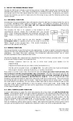
To delete the Hard code, press the “Hard Code” button on the CPU board, confirm that you are 
in hard program mode (slow yellow flash) and press the Bell key or wait 30 seconds. 
 
To  delete the Program code, put the unit into program mode (fast yellow flash) from the 

“Prgm Code” button or from the existing Program code.  Enter 0-0 and press the Bell key or wait 
five seconds.  You’ll see the two red confirmation flashes.  You’ll need to then press the Bell key 
again to exit program mode or wait 30 seconds.  Note that it can be considered logical to 
operate without a Program code.  It is more difficult to put the unit into program mode (it can 
only be done from the “Prgm Code” button in the CPU board) but User codes can still be changed 
and some users may feel that this is a more secure code changing procedure. 

 
To delete any individual User code, put the unit into program mode (fast yellow flash) from 
the “Prgm Code” button or from the existing Program code.  Enter the prefix for the code you 
wish to delete (01 - 59) and press the Bell key or wait five seconds.  You’ll see the two red 
flashes.  You’ll then need to press the Bell key again to exit program mode or wait 30 seconds. 

 
An alternate method to delete any individual User code when you know the actual code 
but not the two digit prefix 
is as follows.  Put the unit into program mode (fast yellow flash) 
from the “Prgm Code” button or from the existing Program code.  Enter 7-9 followed 
immediately by the complete code you wish to delete.  If it’s a seven digit code you’ll 

Summary of Contents for Securitron DK-26

Page 1: ...500 16900 Rev D 12 11 ASSA ABLOY the global leader in door opening solutions MODEL DK 26 DIGITAL KEYPAD SYSTEM INSTALLATION AND OPERATING INSTRUCTIONS Securitron Magnalock Corp www securitron com Tel...

Page 2: ...PROGRAMMING Page 8 SECTION 4 2 KEYPAD CHANGEABLE PROGRAMMING Page 9 SECTION 4 2 1 CHANGING THE USER AND PROG CODE FROM KEYPAD Page 10 SECTION 4 2 2 ADDING MULTIPLE USER CODES Page 10 SECTION 4 3 MAST...

Page 3: ...eypad is pulled down firmly on to the screw A 3 8 10MM hole is then drilled for the cable After the cable has been pulled through the final screw secures the keypad to the wall Note finally that a bla...

Page 4: ...which could cause the microprocessor to malfunction The MOV should be spliced into the lock power wires as close to the lock as possible Some DC electric locks have internal kickback protection includ...

Page 5: ...om an AC transformer when the DK 26 is used Select a transformer of the same voltage as the lock 12 or 24 The CPU board converts the input AC to DC to operate the lock Make sure the capacity of the tr...

Page 6: ...DK 26 and the lock The DK 26 does not require regulated power but certain specialized electric locks do so follow the rule of matching the power supply to the requirements of the lock DC locks come i...

Page 7: ...to send power to the lock Figure 6 shows how to add external contacts for non timed remote release of the lock for both lock types FIG 6 ADDING EXTERNAL CONTACTS FOR FAIL SAFE AND FAIL SECURE LOCKS NC...

Page 8: ...while its normally open contacts activate the DK 26 In effect the lock is released twice Note that the NC contacts are placed in the circuit before the DK 26 s lock control relay This is to aid possi...

Page 9: ...programming in a situation where the end user is not likely to ever change the code or at least that changes would be rare Fixed programming can be used in lower security traffic control applications...

Page 10: ...ixed code programming 4 2 KEYPAD CHANGEABLE PROGRAMMING In this application two codes are programmed into the DK 26 The first called the Program code acts as a password which allows changing the User...

Page 11: ...ately by a new 2 7 digit User code Wait 5 seconds Note two red LED flashes for confirmation note rapid yellow flashing LED returns Press Bell key to terminate program mode or wait 30 seconds Re enter...

Page 12: ...code The unit could not be put into program mode from the keypad The DK 26 however avoids this problem by rejecting any code that is a subset of another code in memory It signals this rejection by sh...

Page 13: ...y by entering a User code and then secured all night by entering a User code again When you have enabled toggle mode activation of the REX input will successively energize and deenergize the lock cont...

Page 14: ...inary operation must be via one or more User codes see Section 4 2 for programming Program the Hard code as your duress code see Section 4 1 Put the unit in program mode and enter 7 5 You will see the...

Page 15: ...e simply by using the second pole of the lock control relay to shunt the door switch see Section 7 3 Generally you mount a Sonalert on the CPU board enclosure It will sound if the door is left open to...

Page 16: ...e terminals 7 3 ALARM SYSTEM SHUNTING The DK 26 s lock control relay is of the double pole double throw type Note that in all the other drawings in this manual we show only one of the poles being used...

Page 17: ...K 26 is often used with Securitron s Touch Sense Bar and magnetic lock The following drawing shows wiring for this particular configuration Note that the REX input is not used Since touching the bar o...

Page 18: ...timer Two digit codes must be entered from 01 to 99 seconds Default is 5 seconds Entering 00 sets toggle mode APPENDIX B TROUBLESHOOTING Note first that the DK 26 replaces older Securitron keypads the...

Page 19: ...nt through the PolySwitch trips it so that it clamps the current down to roughly 100 mA The PolySwitch will continue to clamp until all power is removed for about 5 seconds It is not enough to correct...

Page 20: ...ace the keypad for full operation PROBLEM Unit beeps when keys are pressed but does not accept programming If the problem occurs on initial installation usually it s caused by misunderstanding the pro...

Page 21: ...ry slot 45 You test the code by re entering 4 5 1 2 and the door opens because the sequence includes the real code 1 2 Later it will be noticed that the door is opening on 1 2 as this is such a simple...

Page 22: ...a fail secure lock is operated from the same supply as the DK 26 When the lock is energized it may draw too much power for the power source This reduces the voltage and these voltage swings can crash...

Page 23: ......

Reviews: