background image

Page 4.

08.11.11

Step 16: Installing Intermediate Section Hardware

Note:

 “Intermediate” refers to sections above the bottom section and below 

the top section.

Place the second section face down on the padded saw horses.

Install the #2 Roller HInges and Rollers (#3 for 3 section doors) as shown on 

Page 2, Step 6. 

Install the Center Hinge(s) as shown on Page 2, Step 7.

Note:

 Install locks if required or provided. See Supplement Page 1 or 

instructions provided with the lock for details. 

Note:

 If additional reinforcement (struts) are supplied or required with your 

door, refer to page 8, for proper location.


Note:

 Begin with Page 5, Step 21 for Strut Installation instructions.

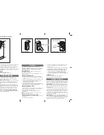
Step 17: Stacking Intermediate Section(s) in Opening

Carefully lift the Intermediate Section, with the rollers, roller carriers, center 

hinges, and struts (if required) to the top. Slide the rollers down into the 

track (Figure 8). Slowly lower the section down onto the bottom section that 

you stacked earlier (Figure 9).

Step 18: Center Hinge(s) Installation

Once the section is in place, push up the upper leave(s) of the Center 

Hinge(s) and attach to the section above with (2) 1/4”x 1” TEK Screws 

(Figure 10).

Step 19: Roller Hinge Installation (Left & Right)

Once the section is in place, push up the upper leave(s) of the Roller 

Hinge(s) and attach to the section above with (2) 1/4”x 1” TEK Screws 

(Figure 11).

Note:

 Repeat steps 16-19 for each intermediate section required 

(Figure 12).


Figure 8

If lock is required, 

install in this section

Intermediate

Intermediate

Intermediate

Bottom

Bottom

Left side shown

Figure 9

Figure 10

Figure 12

Figure 11

TEK  Screws

TEK  Screws

Open for Remaining Instructions

Summary of Contents for Highlands HI1000 - HI2000 - HI3000

Page 1: ...OL3200 OL3138 Dilworth Court DC3200 DC3138 Concord CC4000 Supplemental Installation Instructions Included IMPORTANT Headroom Required Fasteners Actual Size 1 4 20 x 2 1 2 1 5 8 for 1 3 8 thick doors...

Page 2: ...re 4B Repeat this procedure for the right end stile Note Holes in the stiles may not line up with all fixtures handles and locks Use a 3 32 drill bit to start pilot holes for fasteners where pre drill...

Page 3: ...slot of the Flag Bracket to the top of the Vertical Track with 2 1 4 x 5 8 Track Splice Bolts and 2 1 4 20 Hex Nuts Note 1 4 20 Hex Nuts always go on the outside of the track Step 13 Positioning the...

Page 4: ...ully lift the Intermediate Section with the rollers roller carriers center hinges and struts if required to the top Slide the rollers down into the track Figure 8 Slowly lower the section down onto th...

Page 5: ...top corner of the end stiles Secure the fixture to the end stiles with 2 1 4 x 1 TEK Screws Figure 14B Insert Rollers as shown Figure 14B If a strut is required refer to Step 21 for instructions In th...

Page 6: ...to the track position may need to be made later after the springs are installed and the door is opened to maintain the proper spacing Step 31 Adjusting the Top Fixture With the door in the closed pos...

Page 7: ...with your hand until the cable is snug Using only your fingers tighten the 2 Set Screws on the drum finger tight Then turn each screw 1 2 to 1 turn with a wrench Note Do not over tighten the Set Scre...

Page 8: ...ABLOY Entrance Systems RECOMMENDS THAT YOU CONTACT YOUR LOCAL BUILDING OFFICIAL FOR SPECIFIC WIND LOAD REQUIREMENTS IN YOUR AREA MANY ASSA ABLOY DOORS HAVE ENGINEERING DRAWINGS TO MEET WIND LOAD REQU...

Reviews: