background image

V1.0                                   Vig103M Motherboard Manual 

29 

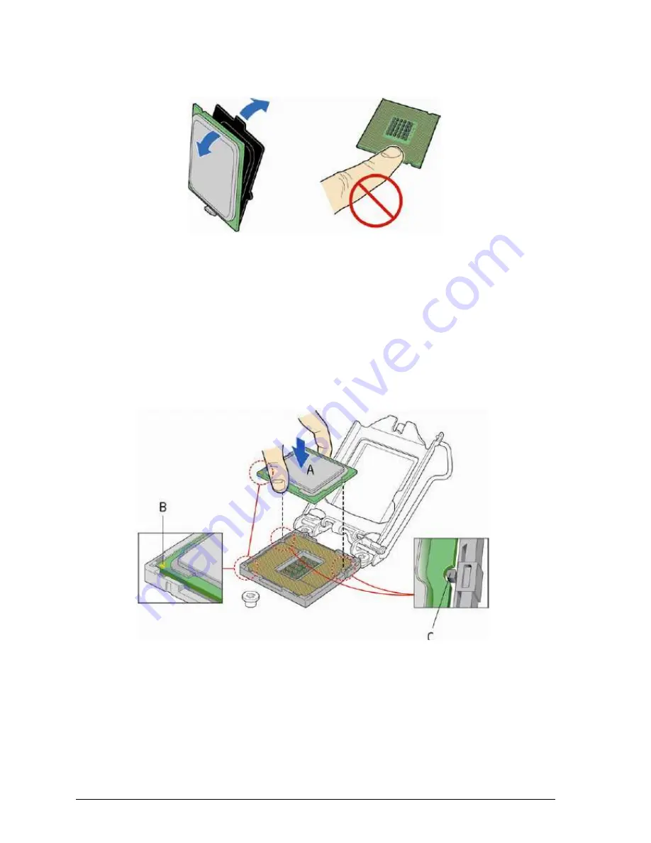
3.  Remove  the  processor  from  its  protective  cover.  Hold  the  processor  only  at  the 

edges, being careful not to touch the bottom of the processor (see Figure 24). 


Figure 194:

 Remove the processor from the protective cover 


Note:

 Do not discard the processor cover. Always replace the processor cover if you 

remove the processor from the socket. 

 
4.  Hold the processor with your thumb and index finger oriented as shown in Figure  25 

to align your fingers with the socket finger cut-outs. Make sure that the processor Pin 
1 indicator (gold triangle) is aligned with the Pin 1 chamfer on the socket (Figure 25, 
B)  and  that  the notches  on  the processor  align  with  the  posts  on the  socket  (Figure 
25,  C).  Lower  the  processor  straight  down  without  tilting  or  sliding  it  in  the  socket 
(Figure 25, A). 


Figure 205:

 Install the processor 


Summary of Contents for Vig103M

Page 1: ...C O M P U T E R S N E T W O R K S S O L U T I O N S 933 Vig103M Vig730M Motherboard Manual ...

Page 2: ...uter system maintains compliance throughout its functional life it is essential you follow these guidelines Install the system according to Viglen s instructions If you open up your Viglen Keep internal cabling in place as supplied Ensure the lid is tightly secured afterwards Do not remove drive bay shields unless installing a CE marked peripheral in its place The clips or bumps around the lips of...

Page 3: ... purchaser for backup Copyright 2015 XMA Limited All Rights Reserved Vig103M Vig730M Manual Version 1 1 Liability No warranty or representation either expressed or implied is made with respect to this documentation its quality performance merchantability or fitness for a particular purpose As a result the documentation is licensed as is and you the licensee are assuming the entire risk as to its q...

Page 4: ...ettings 18 System Board Jumper Settings 19 Motherboard Connectors 20 Upgrading the CPU 28 Installing Removing Memory Modules 32 Replacing the Clock CMOS RAM Battery 34 Chapter 3 Solving Problems 35 Resetting the System 35 Troubleshooting Procedures 36 Problems Suggestions 37 Chapter 4 System BIOS 39 What is the BIOS 39 The Power On Sequence 39 Managing and updating BIOS 40 BIOS Setup Program 41 BI...

Page 5: ...h your multimedia creation experience The Vig103M Motherboard supports 6th generation Intel Core i3 i5 and i7 processors as well as being Microsoft Windows 7 8 1 and Windows 10 WHQL certified This manual contains technical information about the Viglen Vig103M motherboard and other hardware components inside your computer If you are new to computers we recommend that you read the user guide first I...

Page 6: ...rated memory controller Chipset Intel H110M Chipset Memory 2x DIMM DDR4 2133MHz non ECC un buffered memory Up to 32GB total Supports Intel Extreme Memory Profile XMP Graphics Integrated graphics support for processors with Intel Graphics Technology o VGA o HDMI Multi VGA output support HDMI D Sub ports o Supports HDMI with max resolution of 4096x2160 24Hz 2560x1600 60Hz o Supports VGA with max res...

Page 7: ...set HD LED Power LED Power On 2 x 5 pin 1 x USB 2 0 Connector 2 x 5 pin 1 x USB 3 0 connector 4 x SATA 6Gb s Ports 1 x TPM Connector 2 x 7 pin 1 x 4 pin ATX 12V Power connector 1 x 24 pin EATX Power connector s 1 x COM Connector 1 x 2 pin CMOS Header Expansion Capabilities 1x PCIe 3 0 x16 slot 2x PCIe 2 0 x1 slots Rear I O Ports 1 x PS 2 keyboard mouse port 1 x D Sub port 1 x HDMI port 1 x LAN RJ ...

Page 8: ...board is designed to support processors with a maximum TDP of 130 W Chipset Intel H110M Chipset Memory This motherboard comes with four Double Data Rate 4 DDR4 Dual Inline Memory Module DIMM sockets A DDR4 module is notched differently from a DDR DDR2 or DDR3 module DO NOT install a DDR DDR2 or DDR3 memory module to the DDR4 slot Figure 2 Vig103M DDR4 DIMM Sockets You may install 2GB 4GB 8GB and 1...

Page 9: ... or less For effective use of memory we recommend that you do any of the following Use a maximum of 3 GB system memory if you are using a 32 bit Windows OS Install a 64 bit Windows OS if you want to install 4GB or more on the motherboard For more details refer to the Microsoft support site at http support microsoft com kb 929605 en us Memory Configurations The Intel Core i7 Intel Core i5 Intel Cor...

Page 10: ...hree display ports activated to drive the display content of same colour depth setting but potentially different refresh rate and resolution settings to all the active display devices connected Extended Desktop is a mode with up to three display ports activated to drive the content with potentially different colour depth refresh rate and resolution settings on each of the active display devices co...

Page 11: ...n audio effects according to the colour of audio jacks Figure 4 Audio Connectors Line In Blue Line In is used for external CD player tape player or other audio devices Line Out Green Line Out is a connector for speakers or headphones Mic in Pink Mic is a connector for microphones Notes If you want to configure a 7 channel audio output Use a chassis with HD audio module in the front panel to suppor...

Page 12: ...de CSMA CD protocol engine LAN connect interface between the PCH and the LAN controller Conventional PCI bus power management ACPI technology support LAN wake capabilities ACPI technology support LAN wake capabilities LAN subsystem software RJ 45 LAN Connector LEDs The two LEDs are built into the RJ 45 LAN connector located on the back panel These LEDs indicate the status of the LAN as shown in Ta...

Page 13: ...hielded cable that meets the requirements for high speed fully rated devices SATA Support The board provides four 6 Gb s SATA connectors which support one device per connector NOTE By default the SATA mode is set to AHCI in the BIOS to improve system performance During Microsoft Windows XP installation you must press F6 to install the AHCI drivers Microsoft Windows Vista Windows 7 and Windows 8 in...

Page 14: ...he BIOS Setup program settings stored in CMOS RAM for example the date and time might not be accurate Replace the battery with an equivalent one BIOS The BIOS provides the Power On Self Test POST the BIOS Setup program and the PCI PCI Express and SATA auto configuration utilities The BIOS is stored in the Serial Peripheral Interface SPI Flash memory device SATA Auto Configuration If you install a ...

Page 15: ...s set pressing Enter at the password prompt of Setup gives the user restricted access to Setup If both the administrator and user passwords are set you must enter either the administrator password or the user password to access Setup Setup options are then available for viewing and changing depending on whether the administrator or user password was entered Setting a user password restricts who ca...

Page 16: ... Header Q SATA3 Port E SoDIMM1 Slot R SATA4 Port F SoDIMM2 Slot S USB2 0 Header G EZ Debug LEDs T Serial Port Connector H External Power Connector U Front Audio Connector I USB3 0 Connector V TPM Module Connector J CMOS Jumper W Mini PCI E 3 0 x16 Slot K Chassis Intrusion Switch Connector X Mini PCI E 2 0 d Slot L S PDIF Out Header Y Mini PCI E Full card Slot M Front Panel Speaker Header Table 3 M...

Page 17: ...se port This port is for a PS 2 mouse 2 USB 2 0 ports These Universal Serial Bus USB ports are for USB 2 0 1 1 devices 3 HDMI port This port is for a High Definition Multimedia Interface HDMI connector and is HDCP compliant allowing playback of HD DVD Blu ray and other protected content 4 VGA Port The DB15 pin female connector is provided for monitor 5 LAN Port The standard RJ 45 LAN jack is for c...

Page 18: ...egulatory compliance required for using and modifying electronic equipment Do not operate the system with the cover removed Always replace the cover before turning on the system As the colours of the wires in the mains lead of this computer may not correspond with the coloured markings identifying the terminals in your plug precede as follows The wire which is coloured green and yellow must be con...

Page 19: ...epartment for upgrading Any work carried out is fully guaranteed Upgrades should only be carried out by persons who are familiar with handling IC s as incorrect installation will invalidate the guarantee Overview of Jumper Settings The Vig103M motherboard contains the latest technology to offer an almost jumperless configuration All Intel Core CPUs are automatically detected and the speed is autom...

Page 20: ...igure 8 Clear CMOS jumper To erase the RTC RAM 1 Power off the computer and unplug the power cord 2 Use a jumper cap to short JBAT1 for about 5 10 seconds 3 Remove the jumper cap from JBAT1 4 Plug the power cord and power on the computer Except when clearing the RTC RAM never set the jumpers Setting the jumpers will cause system boot failure If the steps above do not help remove the on board batte...

Page 21: ...e connectors are for ATX power supply plugs The power supply plugs are designed to fit these connectors in only one orientation Find the proper orientation and push down firmly until the connectors completely fit This connector allows you to connect an ATX 12V 24 pin power supply To connect the ATX 24 pin power supply make sure the plug of the power supply is inserted in the proper orientation and...

Page 22: ...D lights up when you turn on the system power and blinks when the system is in sleep mode Hard disk drive activity LED 2 pin HDD_LED This 2 pin connector is for the HDD Activity LED Connect the HDD Activity LED cable to this connector The HDD LED lights up or flashes when data is read from or written to the HDD ATX power button soft off switch 2 pin PWR_SW This connector is for the system power sw...

Page 23: ...The speaker allows you to hear system beeps and warnings Viglen chassis does not support speaker Figure 111 Speaker connector Front panel audio connector 10 1 pin JAUD1 This connector allows you to connect the front panel audio and is compliant with Intel Front Panel I O Connectivity Design Guide Figure 122 Front panel audio connector ...

Page 24: ...l to this connector when a chassis component is removed or replaced The signal is then generated as a chassis intrusion event By default both pins do not have JCI1 connector connected Figure 13 Chassis intrusion connector CPU and System fan connectors 4 pin CPUFAN1 4 pin SYSFAN1 Connect the fan cables to the fan connectors on the motherboard ensuring that the black wire of each cable matches the g...

Page 25: ...ATA connectors USB 3 1 Gen1 connector 20 1 pin USB3 These connectors allow you to connect a USB 3 1 Gen1 ports on the front panel With an installed USB 3 0 module you can enjoy all the benefits of USB 3 0 including faster data transfer speeds of up to 5Gbps faster charging time for USB chargeable devices optimized power efficiency and backward compatibility with USB 2 0 Figure 146 Front USB3 0 con...

Page 26: ...install the module to a slot opening at the back of the system chassis These USB connectors comply with USB 2 0 specifications and supports up to 480Mbps connection speed Figure 17 Front USB2 0 connector Serial Port COM Connector This connector is used for connecting a serial port with bracket which is used for connecting peripherals such as networks and printers Figure 18 COM connector ...

Page 27: ... module which secures hardware attached to the motherboard and incorporates encrypted keys to reinforce security Figure 19 TPM Connector S PDIF Out Header This header is for digital audio interconnect for audio signal transmission typically using coaxial or RCA connectors Figure 150 S PDIF Out Header ...

Page 28: ... transfer rate Figure 161 PCI Express Slots Note When adding or removing expansion cards make sure that you power off the system first Important When adding or removing expansion cards always turn off the power supply and unplug the power supply power cable from the power outlet Read the expansion card s documentation to check for any necessary additional hardware or software changes ...

Page 29: ...essor and the board To install a processor follow these instructions 1 Unlatch the processor socket lever by pushing it down and away from the socket Figure 22 A B Figure 172 Unlatch the socket lever 2 Rotate the socket lever to lift the load plate away from the socket Figure 23 A Make sure that the load plate is in the fully open position Figure 23 B while being careful not to damage adjacent com...

Page 30: ...r cover if you remove the processor from the socket 4 Hold the processor with your thumb and index finger oriented as shown in Figure 25 to align your fingers with the socket finger cut outs Make sure that the processor Pin 1 indicator gold triangle is aligned with the Pin 1 chamfer on the socket Figure 25 B and that the notches on the processor align with the posts on the socket Figure 25 C Lower...

Page 31: ...ront edge of the load plate slides under the shoulder screw cap as the lever is lowered Latch the socket lever under the load plate tab Figure 26 C and D The socket cover Figure 26 B will pop off as shown Figure 216 Secure the load plate in place 6 Pick up the socket cover and remove it from the desktop board ...

Page 32: ...nnect the processor fan heat sink power cable to the 4 pin processor fan header see Figure 27 A fan with a 4 pin connector as shown in Figure 27 is recommended 1 Make sure the four hooks are in the proper position before you install the cooler Figure 227 Connecting the processor fan ...

Page 33: ...ore You Begin Turn off the computer and all Peripheral devices 2 Remove the computer cover and locate the DIMM sockets 3 Holding the DIMM by the edges remove it from its antistatic package 4 Make sure the clips at either end of the socket are pushed away from the socket 5 Position the DIMM above the socket Align the two small notches in the bottom edge of the DIMM with the keys in the socket Inser...

Page 34: ... to the computer Turn off the computer 3 Remove the computer cover 4 Gently spread the retaining clips at each end of the socket The DIMM pops out of the socket Hold the DIMM by the edges lift it away from the socket and store it in an antistatic package 5 Reinstall and reconnect any parts you removed or disconnected to reach the DIMM sockets Figure 29 Removing Memory Modules ...

Page 35: ...Do not expose batteries to excessive heat or any naked flame Keep all batteries away from children CAUTION Danger of explosion if the battery is incorrectly replaced Replace only with the same or equivalent type recommended by Viglen Discard used batteries according to manufacturer s instructions To replace the battery carry out the following 1 Observe the precautions in Before You Begin 2 Turn of...

Page 36: ...nformation on our web site http www viglen co uk Device drivers and various useful utilities can be downloaded from our ftp site http download viglen co uk files Motherboards Vig103M Resetting the System Before checking your system for hardware problems it is always a good idea to try resetting your computer and see if a re boot can solve the problem Most software related problems can be solved si...

Page 37: ...perating system normally loads from a diskette insert the operating system diskette into the drive 5 Turn on the system If the power indicator does not light but the system seems to be operating normally the indicator is probably defective Monitor the power on self test POST execution Each time you turn on the system the POST checks the system board memory keyboard and certain peripheral devices N...

Page 38: ...orrectly on the system contact the vendor of the software that fails If you check all of the above with no success try clearing CMOS RAM and reconfiguring the system Make sure you have your list of system settings available to re enter because clearing CMOS RAM sets the options to their default values Characters on screen are distorted or incorrect Make sure the brightness and contrast controls ar...

Page 39: ...gured and enabled in Setup Check the drive manufacturer s manual for proper configuration for remote hard disk drive activity Power on light does not go on If the system is operating normally check the connector between the system board and the front panel If OK the light may be defective Prompt doesn t appear after system boots It s probably switched off A serious fault may have occurred consult ...

Page 40: ...your Viglen computer is guaranteed to be fully compatible with the IBM BIOS It has been written by American Megatrends Inc an industrial leader in the field of BIOS software 4 2 The Power On sequence When the computer is first switched on certain instructions in the BIOS are executed to test various parts of the machine This is known as the POST Power On Self Test routine When you switch the compu...

Page 41: ...py the contents of the file to a bootable USB key or CD ROM media 4 Boot the target PC with the device connected or inserted 5 Select F8 during POST to display the Boot Menu and select your bootable device 6 At the DOS prompt Type Flash bat to launch the BIOS updates process 7 Reboot the system once complete 8 Enter the BIOS Setup and Ensure to load the BIOS default settings to ensure system compa...

Page 42: ...ld for reference only Entering BIOS Setup Power on the computer and the system will start POST Power On Self Test process When the message below appears on the screen press F2 or DEL key to enter Setup You can also press F8 when the message below is on screen to bring up the Boot Menu Press Del or F2 to enter BIOS setup Menu If the message disappears before you respond and you still wish to enter ...

Page 43: ...figuration Save Exit For saving settings and exiting the BIOS setup program Table 8 BIOS main menu selection Menu items The highlighted item on the menu bar displays the specific settings for that menu For example selecting System Status shows the system status settings The other items Advanced Overclocking M Flash Security Boot and Save Exit on the menu bar have their respective menu items 4 5 Sy...

Page 44: ...l depending on the installed devices Configuration options Auto Gen1 Gen2 Gen3 PCI Latency Timer This item appears only when you set the TPM Support item to Enabled and allows you to enable or disable the TPM after POST Reboot your system for the changes to take effect Configuration options 32 PCI Bus Clocks 64 PCI Bus Clocks 96 PCI Bus Clocks 128 PCI Bus Clocks 128 PCI Bus Clocks 160 PCI Bus Cloc...

Page 45: ...his item enables or disables the SATA3 port support Configuration options Enabled Disabled SATA4 Hot Plug This item enables or disables the SATA4 port support Configuration options Enabled Disabled HD Audio Controller Allows enabling or disabling the High Definition Audio controller Configuration options Enabled Disabled HPET This item enables or disables High Precision Event Timer support Configu...

Page 46: ...F8h IRQ 4 IO 3F8h IRQ 3 4 5 6 7 9 10 11 12 IO 2F8h IRQ 3 4 5 6 7 9 10 11 12 IO 3E8h IRQ 3 4 5 6 7 9 10 11 12 IO 2E8h IRQ 3 4 5 6 7 9 10 11 12 4 6 7 Hardware Monitor Allows you to monitor the hardware status CPU Smart Fan Control Allows you to enable or disable the CPU Smart Fan Control Configuration options Enabled Disabled SYS Fan1 Smart Fan Control Allows you to enable or disable the System Smar...

Page 47: ...By This item is for selecting the wake up event for BIOS or operating system Configuration options BIOS OS Resume by RTC Alarm This item is for enabling or disabling wake up event by RTC Alarm Configuration options Enabled Disabled Resume by PCI E Device Allows you to enable or disable wake up event by PCI express device Enable this option for resume from sleep mode by USB device for third party s...

Page 48: ...ng menu items Incorrect field values can cause the system to malfunction The configuration options for this section vary depending on the CPU and DIMM model installed on the motherboard Figure 34 Overclocking 4 8 M Flash The M Flash menu is for selecting a BIOS file to update the BIOS and ME Figure 35 M Flash ...

Page 49: ...sword we recommend that you enter the administrator password for accessing the system Otherwise you might be able to see or change only selected fields in the BIOS setup program To set an administrator password 1 Select the Administrator Password item and press Enter 2 From the Create New Password box key in a password then press Enter 3 Confirm the password when prompted To change an administrato...

Page 50: ...press Enter 2 From the Create New Password box key in a password then press Enter 3 Confirm the password when prompted To change a user password 1 Select the User Password item and press Enter 2 From the Enter Current Password box key in the current password then press Enter 3 From the Create New Password box key in a new password then press Enter 4 Confirm the password when prompted To clear the ...

Page 51: ...r disable CMOS to be resumed when system cannot boot to OS and reboot repeatedly Configuration options Enabled Disabled Boot mode select This item sets the system boot mode from legacy or UEFI architecture depending on OS installation requirement Configuration options Legacy UEFI UEFI Boot Option 1 13 Allows you to set the system boot order Configuration options CD DVD Hard Disk Network USB Key US...

Page 52: ...e finished making your selections choose this option from the Exit menu to ensure the values you selected are saved When you select this option or if you press F10 a confirmation window appears Select Yes to save changes and exit Save Changes Choose this option from the Exit menu to ensure the values you selected are saved Discard Changes Choose this option from the Exit menu to ensure the values ...

Page 53: ...d Windows OS Configuration Windows 8 1 10 WHQL Support Enabled Fast Boot Enabled Advanced Windows OS Configuration Secure Boot Secure Boot Support Enabled Secure Boot Mode Custom Advanced Windows OS Configuration Secure Boot Key Management Provision Factory Default Keys Enabled Note Please ensure the changes of the following settings are performed by personnel with some previous experience knowled...

Page 54: ...ttings have been changed press Esc or the Back Button to go back to the Advanced Menu 4 From the Advanced menu navigate to Windows OS Configuration 5 In Integrated Peripherals change following settings for Windows 8 1 10 Windows 8 1 10 WHQL Support Enabled Fast Boot Enabled Figure 41 Windows OS Configuration 6 Select Secure Boot 7 In Secure Boot change following settings Secure Boot Support Enable...

Page 55: ...on Factory Default Keys and set to Enabled Figure 43 Key Management 10 Press F10 to Save and exit If you need to check changes have been saved go back into BIOS after reboot and navigate into Secure Boot settings Check that Secure Boot Support state is enabled and Platform Key PK state is Loaded ...

Page 56: ... must be changed to boot into Legacy BIOS mode non UEFI Mode For Windows 7 operating system BIOS should be configured as per below settings Advanced Integrated Peripherals Network Stack Disabled Figure 44 Integrated Peripherals Win 7 Advanced Windows OS Configuration Windows 7 Installation Disabled Fast Boot Disabled Figure 45 Windows OS Configuration Win 7 ...

Page 57: ...ay like to answer and return to Viglen This will help Viglen help to keep and improve the standard of their manuals 1 Is the information provided in this and other manuals clear enough 2 What could be added to the manual to improve it 3 Does the manual go into enough detail 4 Would you like an on line version of this manual 5 How do you rate the Viglen Technical support and Service Departments ...

Page 58: ...Are there any technological improvements that could be made to the system 7 Other points you would like to mention Please return this slip to Product Development Dept XMA Ltd 7 Handley Page Way Colney Street St Albans Hertfordshire AL2 2DQ ...

Page 59: ...V1 0 Vig103M Motherboard Manual 58 Notes ...

Reviews: