background image

1 7

1 7

1 7

1 7

1 7

2.5  Installation of Memor

2.5  Installation of Memor

2.5  Installation of Memor

2.5  Installation of Memor

2.5  Installation of Memory Modules (DIMM)

y Modules (DIMM)

y Modules (DIMM)

y Modules (DIMM)

y Modules (DIMM)

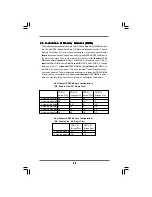
This motherboard provides four 240-pin DDR2 (Double Data Rate 2) DIMM slots and
two 240-pin DDR3 (Double Data Rate 3) DIMM slots, and supports Dual Channel
Memory Technology. For dual channel configuration, you always need to install

identical

 (the same brand, speed, size and chip-type) DDR2/DDR3 DIMM pair in

the slots of the same color. In other words, you have to install 

identical

 DDR2

DIMM pair in 

Dual Channel A 

(DDRII_1 and DDRII_3; Yellow slots; see p.11 No.6),

identical

 DDR2 DIMM pair in 

Dual Channel B 

(DDRII_2 and DDRII_4; Orange

slots; see p.11 No.7), or 

identical

 DDR3 DIMM pair in 

Dual Channel C 

(DDR3_A1

and DDR3_B1; Green slots; see p.11 No.8), so that Dual Channel Memory Technol-
ogy can be activated. This motherboard also allows you to install four DDR2 DIMMs
for dual channel configuration, and please install 

identical

 DDR2 DIMMs in all four

slots. You may refer to the Dual Channel Memory Configuration Table below.

Dual Channel DDR2 Memory Configurations

(DS: Double Side, SS: Single Side)

         DDRII_1          DDRII_2           DDRII_3           DDRII_4
        (Yellow Slot)    (Orange Slot)   (Yellow Slot)    (Orange Slot)

2 memory modules  SS

         X

       SS

     X

2 memory modules  DS

         X

       DS

     X

2 memory modules  X

         SS

       X

     SS

2 memory modules  X

         DS

       X

     DS

4 memory modules  SS

        SS

       SS

    SS

4 memory modules  DS

        DS

       DS

    DS

        DDR3_A1         DDR3_B1
        (Green Slot)     (Green Slot)

2 memory modules  SS

         SS

2 memory modules  DS

         DS

Dual Channel DDR3 Memory Configurations

(DS: Double Side, SS: Single Side)

Summary of Contents for 4Core1600Twins-P35D

Page 1: ...1 1 1 1 1 4Core1600Twins P35D User Manual Version 1 0 Published February 2008 Copyright 2008 ASRock INC All rights reserved ...

Page 2: ... or implied including but not limited to the implied warran ties or conditions of merchantability or fitness for a particular purpose In no event shall ASRock its directors officers employees or agents be liable for any indirect special incidental or consequential damages including damages for loss of profits loss of business loss of data interruption of business and the like even if ASRock has be...

Page 3: ... Expansion Slots PCI and PCI Express Slots 20 2 7 CrossFireTM Operation Guide 20 2 8 Surround Display Feature 24 2 9 Jumpers Setup 25 2 10 Onboard Headers and Connectors 27 2 11 HDMI_SPDIF Header ConnectionGuide 32 2 12 eSATAII Interface Introduction 33 2 13 SATAII Hard Disk Setup Guide 36 2 14 Serial ATA SATA Serial ATAII SATAII Hard Disks Installation 37 2 15 Hot Plug Function for SATA SATAII HD...

Page 4: ...ration 51 3 3 5 PCIPnP Configuration 53 3 3 6 Floppy Configuration 54 3 3 7 Super IO Configuration 54 3 3 8 USB Configuration 56 3 4 Hardware Health Event Monitoring Screen 56 3 5 Boot Screen 57 3 5 1 Boot Settings Configuration 58 3 6 Security Screen 58 3 7 Exit Screen 59 4 Software Support 4 Software Support 4 Software Support 4 Software Support 4 Software Support 60 60 60 60 60 4 1 Install Oper...

Page 5: ...ny modifications of this manual occur the updated version will be available on ASRock website without further notice You may find the latest VGA cards and CPU support lists on ASRock website as well ASRock website http www asrock com If you require technical support related to this motherboard please visit our website for specific information about the model you are using www asrock com support in...

Page 6: ...2 Memory Technology see CAUTION 4 2 x DDR3 DIMM slots green SupportDDR3 1333 1066 800 non ECC un buffered memory see CAUTION 5 Max capacity 4GB see CAUTION 6 4 x DDR2 DIMM slots yellow and orange SupportDDR2 1066 800 667 non ECC un buffered memory see CAUTION 5 Max capacity 8GB see CAUTION 6 Expansion Slot Supports ATITM CrossFireTM 1 x PCI Express x16 slot 1 x AGI Express slot PCI Express x4 3 x ...

Page 7: ...er see CAUTION 11 BIOS Feature 4Mb AMI BIOS AMI Legal BIOS Supports Plug and Play ACPI 1 1 Compliance Wake Up Events Supports jumperfree AMBIOS 2 3 1 Support CPU DRAM NB SB VTT Voltage Multi adjustment Supports I O T Intelligent Overclocking Technology Support CD Drivers Utilities AntiVirus Software Trial Version Unique Feature ASRock OC Tuner see CAUTION 12 Hybrid Booster CPU Frequency Stepless C...

Page 8: ...066 DDR3 800 DDR3 1066 DDR3 1333 1066 DDR2 667 DDR2 800 DDR2 1066 DDR3 800 DDR3 1066 800 DDR2 667 DDR2 800 DDR3 800 DDR2 1066 and DDR3 1333 memory modules will operate in overclocking mode When you use a FSB1600 CPU on this motherboard it will run at DDR2 960 if you adopt a DDR2 1066 memory module When you use a FSB1600 CPU on this motherboard it will run at DDR3 960 if you adopt a DDR3 1066 memor...

Page 9: ...an easy to use wireless local area network WLAN adapter It allows you to create a wireless environment and enjoy the convenience of wireless network connectivity Please visit our website for the availability of ASRock WiFi 802 11g or WiFi 802 11n module ASRock website http www asrock com 12 It is a user friendly ASRock overclocking tool which allows you to surveil your system by hardware monitor f...

Page 10: ...ium 2008 and Basic Logo Premium 2008 and Basic Logo Premium 2008 and Basic Logo For system integrators and users who purchase this motherboard and plan to submit Windows VistaTM Premium 2008 and Basic logo please follow below table for minimum hardware requirements CPU Celeron 420 Memory 1GB system memory Premium 512MB Single Channel Basic VGA DX10 with WDDM Driver with 128bit VGA memory Premium w...

Page 11: ...OM1 PS2 Mouse PS2 Keyboard ESATAII USB 2 0 T USB0 B USB1 Top RJ 45 USB 2 0 T USB2 B USB3 33 34 35 36 ATX12V1 1 PS2_USB_PWR1 Jumper 18 USB 2 0 Header USB6_7 Blue 2 ATX 12V Connector ATX12V1 19 USB 2 0 Header USB4_5 Blue 3 CPU Fan Connector CPU_FAN1 20 USB 2 0 Header USB8_9 Blue 4 775 Pin CPU Socket 21 South Bridge Controller 5 North Bridge Controller 22 SPI BIOS Chip 6 2 x 240 pin DDR2 DIMM Slots 2...

Page 12: ... click ok Choose 2CH 4CH 6CH or 8CH and then you are allowed to select Realtek HDA Primary output to use Rear Speaker Central Bass and Front Speaker or select Realtek HDA Audio 2nd output to use front panel audio 6 7 1 2 4 3 5 8 9 10 11 12 13 14 If you use 2 channel speaker please connect the speaker s plug into Front Speaker Jack See the table below for connection details in accordance with the t...

Page 13: ...re installation Precautions 2 2 Pre installation Precautions 2 2 Pre installation Precautions 2 2 Pre installation Precautions Take note of the following precautions before you install motherboard components or change any motherboard settings 1 Unplug the power cord from the wall socket before touching any component 2 To avoid damaging the motherboard components due to static electricity NEVER pla...

Page 14: ...ed Step 1 Open the socket Step 1 1 Disengaging the lever by depressing down and out on the hook to clear retention tab Step 1 2 Rotate the load lever to fully open po sition at approximately 135 degrees Step 1 3 Rotate the load plate to fully open po sition at approximately 100 degrees Step 2 Insert the 775 LAND CPU Step 2 1 Hold the CPU by the edges where are marked with black lines Step 2 2 Orie...

Page 15: ...eft hand index finger and thumb to support the load plate edge engage PnP cap with right hand thumb and peel the cap from the socket while pressing on center of PnP cap to assist in removal 1 It is recommended to use the cap tab to handle and avoid kicking off the PnP cap 2 This cap must be placed if returning the motherboard for after service Step 4 Close the socket Step 4 1 Rotate the load plate...

Page 16: ... proper installation please kindly refer to the instruction manuals of your CPU fan and heatsink Below is an example to illustrate the installation of the heatsink for 775 LAND CPU Step 1 Apply thermal interface material onto center of IHS on the socket surface Step 2 Place the heatsink onto the socket Ensure fan cables are oriented on side closest to the CPU fan connector on the motherboard CPU_F...

Page 17: ... in Dual Channel B DDRII_2 and DDRII_4 Orange slots see p 11No 7 or identical DDR3 DIMM pair in Dual Channel C DDR3_A1 and DDR3_B1 Green slots see p 11No 8 so that Dual Channel Memory Technol ogy can be activated This motherboard also allows you to install fourDDR2DIMMs for dual channel configuration and please install identical DDR2 DIMMs in all four slots You may refer to the Dual Channel Memory...

Page 18: ... unable to acti vate the Dual Channel Memory Technology If only one memory module is installed in the DDR3 DIMM slots on this motherboard it is unable to activate the Dual Channel Memory Technology 3 If a pair of memory modules is NOT installed in the same Dual Channel for example installing a pair of memory modules in DDRII_1 and DDRII_2 it is unable to activate the Dual Channel Memory Technology...

Page 19: ...essing the retaining clips outward Step 2 Align a DIMM on the slot such that the notch on the DIMM matches the break on the slot The DIMM only fits in one correct orientation It will cause permanent damage to the motherboard and the DIMM if you force the DIMM into the slot at incorrect orientation Step 3 Firmly insert the DIMM into the slot until the retaining clips at both ends fully snap back in...

Page 20: ...xpress Slots Slots Slots Slots Slots There are 3 PCI slots 1 PCI Express slot and 1 AGI Express slot PCI Express x4 on this motherboard PCI slots PCI slots are used to install expansion cards that have the 32 bit PCI interface PCIE slots PCIE1 PCIE x16 slot is used for PCI Express cards with x16 lane width graphics cards AGI Express slot PCI Express x4 AGI Express slot PCI Express x4 is used to in...

Page 21: ...ifferent CrossFireTM cards may require different methods to enable CrossFireTM feature In below procedures we use Radeon 2600XT as the example graphics card For other CrossFireTM cards that ATITM has released or will release in the future please refer to ATITM graphics card manuals for detailed installation guide It is recommended to use 500 Watt power supply or greater to perform the benefit of C...

Page 22: ...s cards by installing two CrossFireTM Bridge on CrossFireTM Bridge Interconnects on the top of Radeon graphics cards CrossFireTM Bridge is provided with the graphics card you purchase not bundled with this motherboard Please refer to your graphics card vendor for details Step 5 Connect the DVI monitor cable to the DVI connector on the Radeon graphics card on PCIE1 slot You may use the DVI to D Sub...

Page 23: ... in your system there is no need to download it again http www microsoft com windowsxp sp2 default mspx B You must have Microsoft NET Framework installed prior to downloading and installing the CATALYST Control Center Please check Microsoft website for details For Windows VistaTM OS Install the CATALYST Control Center Please check AMD website for details Step 9 Restart your computer Step 10 Instal...

Page 24: ...registered trademark of ATITM Technologies Inc and is used only for identification or explanation and to the owners benefit without intent to infringe For further information of ATITM CrossFireTM technology please check AMD website for updates and details 2 8 Surround Display Feature 2 8 Surround Display Feature 2 8 Surround Display Feature 2 8 Surround Display Feature 2 8 Surround Display Feature...

Page 25: ...tandby current provided by power supply Clear CMOS Jumper CLRCMOS1 see p 11 No 10 Note CLRCMOS1 allows you to clear the data in CMOS The data in CMOS includes system setup information such as system password date time and system setup parameters To clear and reset the system parameters to default setup please turn off the computer and unplug the power cord from the power supply After waiting for 1...

Page 26: ...le on this motherboard you need to adjust the jumpers Please short pin4 pin5 for FSB2 Otherwise the CPU and memory module may not work properly on this motherboard Please refer to below jumper settings Note3 If you use a FSB1066 CPU and adopt a DDR2 1066 memory module on this motherboard you need to adjust the jumpers Please short pin2 pin3 for FSB3 Otherwise the CPU and memory module may not work...

Page 27: ...ion of your IDE device vendor for the details Serial ATAII Connectors These four SerialATAII SATAII SATAII_1 Port0 connectors support SATA data see p 11 No 12 cables for internal storage SATAII_2 Port1 devices The current SATAII see p 11 No 16 interface allows up to 3 0 Gb s SATAII_5 Port4 data transfer rate see p 11 No 11 SATAII_6 Port5 see p 11 No 17 SATAII_6 Port5 connector can be used for inte...

Page 28: ...ATA Please connect the black end of Power Cable SATA power cable to the power Optional connector on each drive Then connect the white end of SATA power cable to the power connector of the power supply eSATAII connect to the SATA HDD powerconnector connect to the powersupply USB_PWR USB_PWR P 5 P 5 P 4 P 4 GND GND DUMMY 1 USB_PWR USB_PWR P 7 P 7 P 6 P 6 GND GND DUMMY 1 1 USB_PWR P 8 GND DUMMY USB_P...

Page 29: ...i 802 11g or WiFi 802 11n module an easy to use wireless local area network WLAN adapter It allows you to create a wirelessenvironmentandenjoythe convenience of wireless network connectivity 1 USB 5V_1 NC NC GND1 PLTRST 3SVB USB 5V_1 D0 D0 GND1 PME 1 High Definition Audio supports Jack Sensing but the panel wire on the chassis must support HDA to function correctly Please follow the instruction in...

Page 30: ...ck the icon on the lower right hand taskbar to enter Realtek HD Audio Manager For Windows 2000 XP XP 64 bit OS Click Audio I O select Connector Settings choose Disable front panel jack detection and save the change by clicking OK For Windows VistaTM VistaTM 64 bit OS Click the right top Folder icon choose Disable front panel jack detection and save the change by clicking OK 4 3 2 1 GND 12V CPU_FAN...

Page 31: ...DIFHeader HDMI_SPDIF header providing 3 pin HDMI_SPDIF1 SPDIF audio output to HDMI VGA see p 11 No 26 card allows the system to connect HDMI Digital TV projector LCD devices Please connect the HDMI_SPDIF connector of HDMI VGA card to this header HDMI_SPDIFCable Please connect the black end A Optional of HDMI_SPDIF cable to the HDMI_SPDIF header on the motherboard Then connect the white end B or C ...

Page 32: ...refer to the user manual of HDMI VGA card vendor Incorrect connection may cause permanent damage to this motherboard and the HDMI VGA card white end 2 pin B white end 3 pin C Please do not connect the white end of HDMI_SPDIF cable to the wrong connector of HDMI VGA card or other VGA card Otherwise the motherboard and the VGA card may be damaged For example this picture shows the wrong example of c...

Page 33: ...ver eSATAII provides the data transfer rate up to 3000Mb s which is much higher than USB 2 0 and IEEE 1394 and still keeps the convenience of Hot Plug feature Therefore on the basis of the advantageous transfer speed and the facilitating mobile capability in the near future eSATAII will replace USB 2 0 and IEEE 1394 to be a trend for external interface eSATAII connector eSATAII NOTE 1 If you set C...

Page 34: ...t eSATAII device and the eSATAII port of the I O shield Connect the SATA data cable to the orange SATAII connector SATAII_6 Port5 Connect the SATA data cable to the eSATAII connector eSATAII 1 In order to enable the eSATAII port of the I O shield you need to connect the orange SATAII connector SATAII_6 Port5 see p 11 No 17 and the eSATAII connector eSATAII see p 11 No 36 with a SATA data cable fir...

Page 35: ...35 35 35 35 35 Comparison between eSATAII and other devices IEEE 1394 400Mb s USB 2 0 480Mb s SATA 1 5Gb s 1500Mb s eSATAII SATAII 3 0Gb s 3000Mb s ...

Page 36: ...sk may fail to run at SATAII mode Western Digital If pin 5 and pin 6 are shorted SATA 1 5Gb s will be enabled On the other hand if you want to enable SATAII 3 0Gb s please remove the jumpers from pin 5 and pin 6 SAMSUNG If pin 3 and pin 4 are shorted SATA 1 5Gb s will be enabled On the other hand if you want to enable SATAII 3 0Gb s please remove the jumpers from pin 3 and pin 4 HITACHI Please use...

Page 37: ...15 Hot Plug F 2 15 Hot Plug F 2 15 Hot Plug Function for SA unction for SA unction for SA unction for SA unction for SAT T T T TA SA A SA A SA A SA A SAT T T T TAII HDDs and eSA AII HDDs and eSA AII HDDs and eSA AII HDDs and eSA AII HDDs and eSAT T T T TAII AII AII AII AII Devices Devices Devices Devices Devices This motherboard supports Hot Plug function for SATA SATAII eSATAII Devices in AHCI mo...

Page 38: ...you process the SATA SATAII HDD Hot Plug please check below cable accessories from the motherboard gift box pack A 7 pin SATA data cable B SATA power cable with SATA 15 pin power connector interface The SATA 15 pin power connector Black connect to SATA SATAII HDD Points of attention before you process the Hot Plug 1 Below operation procedure is designed only for our motherboard which supports SATA...

Page 39: ...DD Connect SATA data cable to the SATA SATAII HDD How to Hot Unplug a SATA SATAII HDD Points of attention before you process the Hot Unplug Please do follow below instruction sequence to process the Hot Unplug improper procedure will cause the SATA SATAII HDD damage and data loss Please connect SATA power cable 1x4 pin end White to the power supply 1x4 pin cable Step 1 Step 2 Step 3 Step 4 Step 2 ...

Page 40: ...AID Functions 64 bit Without RAID Functions 64 bit Without RAID Functions 64 bit Without RAID Functions If you want to install Windows 2000 XP XP 64 bit VistaTM VistaTM 64 bit OS on your SATA SATAII HDDs without RAID functions please follow below procedures according to the OS you install 2 18 1 Installing Windows 2 18 1 Installing Windows 2 18 1 Installing Windows 2 18 1 Installing Windows 2 18 1...

Page 41: ...ta Vista Vista VistaTM TM TM TM TM Vista Vista Vista Vista VistaTM TM TM TM TM 64 bit 64 bit 64 bit 64 bit 64 bit W W W W Without RAID F ithout RAID F ithout RAID F ithout RAID F ithout RAID Functions unctions unctions unctions unctions If you want to install Windows VistaTM VistaTM 64 bit OS on your SATA SATAII HDDs without RAID functions please follow below steps Using SATA SATAII HDDs and eSATA...

Page 42: ...fore CPU FSB is untied during overclocking but PCI PCIE buses are in the fixed mode so that FSB can operate under a more stable overclocking environment Please refer to the warning on page 8 for the possible overclocking risk before you apply Untied Overclocking Technology Using SATA SATAII HDDs and eSATAII devices without NCQ function STEP 1 Set up BIOS A Enter BIOS SETUP UTILITY Advanced screen ...

Page 43: ...ressing the reset button on the system chassis You may also restart by turning the system off and then back on Because the BIOS software is constantly being updated the following BIOS setup screens and descriptions are for refer ence purpose only and they may not exactly match what you see on your screen 3 1 1 3 1 1 3 1 1 3 1 1 3 1 1 BIOS Menu Bar BIOS Menu Bar BIOS Menu Bar BIOS Menu Bar BIOS Men...

Page 44: ...r the BIOS SETUP UTILITY the Main screen will appear and display the system overview System Time Hour Minute Second Use this item to specify the system time System Date Day Month Date Year Use this item to specify the system date BIOS SETUP UTILITY Main Advanced H W Monitor Boot Security Exit System Overview System Time System Date 00 09 Tue 02 12 2008 Use Enter TAB or SHIFT TAB to select a field ...

Page 45: ...nfiguration Chipset Configuration IDE Configuration PCIPnP Configuration Floppy Configuration SuperIO Configuration USB Configuration ACPI Configuration 3 3 3 3 3 3 3 3 3 3 Advanced Screen Advanced Screen Advanced Screen Advanced Screen Advanced Screen In this section you may set the configurations for the following items CPU Configuration Chipset Configuration ACPI Configuration IDE Configuration...

Page 46: ...or better system stability Ratio Status This is a read only item which displays whether the ratio status of this motherboard is Locked or Unlocked If it shows Unlocked you will find an item Ratio CMOS Setting appears to allow you changing the ratio value of this motherboard Ratio Actual Value This is a read only item which displays the ratio actual value of this motherboard BIOS SETUP UTILITY CPU ...

Page 47: ...t No Excute Memory Protection Hyper Threading Technology To enable this feature it requires a computer system with an Intel Pentium 4 processor that supports Hyper Threading technology and an operating system that includes optimization for this technology such as Microsoft Windows XP Set to Enabled if using Microsoft Windows XP or Linux kernel version 2 4 18 or higher This option will be hidden if...

Page 48: ...adjust the means of memory accessing Configuration options for DDR2 memory modules are 3 4 5 6 and Auto Configuration options for DDR3 memory modules are are 5 6 7 8 9 and Auto DRAM RAS to CAS Delay This controls the latency between the DRAM active command and the read write command Configuration options Auto 3 DRAM Clocks 4 DRAM Clocks 5 DRAM Clocks and 6 DRAM Clocks DRAM RAS Precharge This contr...

Page 49: ...e of this feature is Auto DRAM Voltage Use this to select DRAM Voltage Configuration options for DDR2 memory modules Auto 1 79V 1 85V 1 90V 1 96V 2 02V 2 08V 2 14V 2 20V 2 31V 2 37V 2 42V 2 48V 2 54V 2 60V 2 66V and 2 72V Configuration options for DDR3 memory modules Auto 1 47V 1 53V 1 64V 1 71V 1 76V 1 82V 1 88V 1 99V 2 05V 2 11V 2 16V 2 23V 2 28V 2 34V 2 40V and 2 66V The default value of this f...

Page 50: ...if the OS supports it If you set this item to Disabled the function Repost Video on STR Resume will be hidden Repost Video on STR Resume This feature allows you to repost video on STR resume STR refers to suspend to RAM Restore on AC Power Loss This allows you to set the power state after an unexpected AC power loss If Power Off is selected the AC power remains off when the power recovers If Power...

Page 51: ...T Table The default value is Disabled Please set this option to Enabled if you plan to use this motherboard to submit Windows VistaTM certification 3 3 4 3 3 4 3 3 4 3 3 4 3 3 4IDE Configuration IDE Configuration IDE Configuration IDE Configuration IDE Configuration SATAII Configuration Please select Compatible when you install legacy OS If native OS Windows 2000 XP is installed please select Enha...

Page 52: ... Inc Advanced Type LBA Large Mode Block Multi Sector Transfer PIO Mode DMA Mode S M A R T 32Bit Data Transfer Auto Auto Auto Auto Auto Disabled Enabled Device Vendor Size LBA Mode Block Mode PIO Mode Async DMA Ultra DMA S M A R T Hard Disk ST340014A 40 0 GB Supported 16Sectors 4 MultiWord DMA 2 Ultra DMA 5 Supported IDE Device Configuration You may set the IDE configuration for the device that you...

Page 53: ...ion PCIPnP Configuration PCI Latency Timer The default value is 32 It is recommended to keep the default value unless the installed PCI expansion cards specifications require other settings PCI IDE BusMaster Use this item to enable or disable the PCI IDE BusMaster feature DMA Mode DMA capability allows the improved transfer speed and data integrity for com patible IDE devices S M A R T Use this it...

Page 54: ...t Configuration options Disabled 2F8 IRQ3 and 2E8 IRQ3 If you plan to use ASRock DeskExpress on this motherboard please keep this item on Disabled option BIOS SETUP UTILITY Floppy Configuration Select the type of floppy drive connected to the system Select Screen Select Item Change Option F1 General Help F9 Load Defaults F10 Save and Exit ESC Exit v02 54 C Copyright 1985 2005 American Megatrends I...

Page 55: ...s ECP EPP If this option is set to ECP EPP it will show the EPP version in the following item EPP Version Configuration options Normal Bi Directional and ECP EPP EPP Version Use this item to set the EPP version Configuration options 1 9 and 1 7 ECP Mode DMA Channel Use this item to set the ECP mode DMA channel Configuration options DMA0 DMA1 and DMA3 Parallel Port IRQ Use this item to set the IRQ ...

Page 56: ... this section it allows you to monitor the status of the hardware on your system including the parameters of the CPU temperature motherboard temperature CPU fan speed chassis fan speed and the critical voltage BIOS SETUP UTILITY Hardware Health Event Monitoring Select Screen Select Item F1 General Help F9 Load Defaults F10 Save and Exit ESC Exit v02 54 C Copyright 1985 2003 American Megatrends Inc...

Page 57: ... ROM C USB CPU Quiet Fan This item allows you to identify the temperature of CPU fan If you set this option as Disabled the CPU fan will operate in full speed If you set this option as Enabled you will find the items Target CPU Temperature C Tolerance C and Minimun Fan Speed appear to allow you adjusting them The default value is Disabled You are allowed to enable this function only when you insta...

Page 58: ...assword for the system For the user password you may also clear it BIOS SETUP UTILITY Main Advanced H W Monitor Boot Exit Install or Change the password Select Screen Select Item Enter Change F1 General Help F10 Save and Exit ESC Exit F9 Load Defaults v02 54 C Copyright 1985 2005 American Megatrends Inc Security Change Supervisor Password Change User Password Security Settings Supervisor Password ...

Page 59: ...n you select this option it will pop out the following message Dis card changes Select OK to discard all changes Load Optimal Defaults When you select this option it will pop out the following message Load optimal defaults Select OK to load the default values for all the setup configurations BIOS SETUP UTILITY Main Advanced H W Monitro Boot Security Exit system setup after saving the changes F10 k...

Page 60: ...g The Support CD Running The Support CD To begin using the support CD insert the CD into your CD ROM drive The CD automatically displays the Main Menu if AUTORUN is enabled in your computer If the Main Menu did not appear automatically locate and double click on the file ASSETUP EXE from the BIN folder in the Support CD to display the menus 4 2 2 4 2 2 4 2 2 4 2 2 4 2 2 Drivers Menu Drivers Menu D...

Reviews: