background image

ELMON inducti ve 71-242  +  ELMON inducti ve 71-942

Betriebsanleitung   

(Original, 

Gülti gkeit siehe letzte Seite

)

ELMON inducti ve 71-242  +  ELMON inducti ve 71-942 Sicherheitsschaltgerät Seite 3-12

Manuel d’uti lisati on   

(

Validité voir la dernière page)

ELMON inducti ve 71-242  +  ELMON inducti ve 71-942

Relais de sécurité

Operati ng Manual   

(

see last page for validity)

ELMON inducti ve 71-242  +  ELMON inducti ve 71-942 Safety Relay

Page 13-22

Page 23-32

English

Fr

anç

ais

Deutsch

Indukti ves Signalübertragungssystem

 / 

Inducti ve signal transmission system

 / 

Système de transmission de signal inducti f

Summary of Contents for ELMON Inductive 71-242

Page 1: ... Manuel d utilisation Validité voir la dernière page ELMON inductive 71 242 ELMON inductive 71 942 Relais de sécurité Operating Manual see last page for validity ELMON inductive 71 242 ELMON inductive 71 942 Safety Relay Page 13 22 Page 23 32 English Français Deutsch Induktives Signalübertragungssystem Inductive signal transmission system Système de transmission de signal inductif ...

Page 2: ...upplémentaires Componenti ausiliari Bijkomende componenten Funktionsprüfung Functional test Contrôle de fonction Controllo funzionale Functiecontrole Sicherheitssensoren reagieren auf Betätigung Safety sensor response to actuation Le senseur de sécurité réagit à l actionnement Il sensore di sicurezza reagisce all azionamento Veiligheidssensor reageert op activering Sicherheitssensoren reagieren au...

Page 3: ...Verwendung 5 5 Systemkomponenten am Tor 6 6 Geräteübersicht 6 6 1 Signalanzeigen 6 6 2 Anschlussklemmen 7 7 Anschluss des Gerätes 7 7 1 Voraussetzungen 7 7 2 Versorgungsspannung 8 7 3 Anschluss feststehender Spulenkern 8 7 4 Anschluss feststehende Sicherheitskontaktleisten 8 7 5 Anschluss Steuerstromkreise 8 7 6 Anschluss der Sicherheitskontaktleisten am Spulenkern SPK 54 8 7 7 Anschluss von mehre...

Page 4: ... anzuwenden Die Installation und Inbetriebnahme der Schutzeinrichtung darf nur durch Fachpersonal erfolgen die mit dieser Betriebsanleitung und den geltenden Vorschriften über Arbeitssicherheit und Unfallverhütung vertraut sind Die Hinweise in dieser Anleitung sind unbedingt zu beachten und einzuhalten Elektrische Arbeiten dürfen nur von Elektrofachkräften durchgeführt werden Sicherheitsvorschrift...

Page 5: ...rschleißfrei überwacht Die feststehenden Sicherheitskontaktleisten werden direkt an das Schaltgerät angeschlossen Das Schaltgerät überwacht diese vier Sicherheitskontaktleistenkreise permanent auf Betätigung oder Unter brechung Kabelbruch Bei einer Störung wird dem entsprechenden Sicherheitskontaktleistenkreis einer der zwei Stop Befehle zugeordnet Stop in Auf Richtung oder Stop in Zu Richtung Um ...

Page 6: ...ehlermeldung vor so wird über die LED Power der Betriebszustand angezeigt an V5 6oderspäter WirdwährenddesBetriebeseininternerFehlerzustandfestgestellt sowirddieFehlermeldung gesichert Die vorhandenen gesicherten Fehlermeldungen werden nacheinander durch die grüne LED Power über die Anzahl Pulse ausgegeben Nach einem Einschaltvorgang sind alle intern gesicherten Fehlermeldungen gelöscht Liegt aktu...

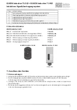
Page 7: ...9 ELMON inductive 71 242 Pin 1 2 feststehender Spulenkern Pin 3 11 Sicherheitskontaktleiste Führungspfosten Öffnen Pin 3 10 Sicherheitskontaktleiste Führungspfosten Schließen Pin 4 5 Relais Ausgang zur Steuerung Stop Öffnen Pin 6 7 Relais Ausgang zur Steuerung Stop Schließen Pin 8 9 Versorgungsspannung 24 V 6 2 Anschlussklemmen Pulse Fehlermeldung 1 Spannungsversorgung außerhalb des gültigen Wertb...

Page 8: ...ese in Reihe geschaltet und die Endleiste mit 8 2 kΩ abgeschlossen ELMON inductive 71 242 Die feststehende n Sicherheitskontaktleiste n für die Zu Bewegung wird werden an das Klemmenpaar 3 10 ange schlossen ELMON inductive 71 942 Die feststehende n Sicherheitskontaktleiste n für die Zu Bewegung wird werden mit dem Steckplatz Stationary Closing verbunden Sollte ein Kanal für die feststehenden Siche...

Page 9: ...ontaktleisten kann bis zu 25 m betragen Vor dem Anschließen der in Serie geschalteten Sicherheitskontaktleisten ist es empfehlenswert den Wider standswert der Verschaltung auszumessen Bei unbetätigter Sicherheitskontaktleiste muss der Widerstand 8 2 kΩ 500 Ω betragen Ist die Sicherheits kontaktleiste betätigt darf der Widerstand 500 Ω nicht überschreiten Sollte ein Kanal nicht genutzt werden muss ...

Page 10: ...ntsprechenden Sicherheitskontakt leiste überprüfen abgequetschte Zuleitungen brüchige Zuleitungen etc Sicherheitskontaktleiste n überprüfen Liegt der Fehler nicht in der Verdrahtung kann die Funktion der Elektronik durch Belegung aller Sicher heitskontaktleisten Eingänge an der ELMON inductive 71 242 ELMON inductive 71 942 Auswertelek tronik Klemmen 3 10 und Klemmen 3 11 und am mitfahrenden Spulen...

Page 11: ...altgerät angeschlossenen Spannungen müssen sicher getrennte Spannungen sein Prü ericht Nr 3525 3024 EG Baumuster Nr 44 205 13 031832 ELMON inductive 71 242 ELMON inductive 71 942 feststehend mitfahrend Nominalwert Rnom 8 2 kΩ 8 2 kΩ Oberer Schaltwert RAO 12 kΩ 20 kΩ Unterer Schaltwert RAU 5 kΩ 2 5 kΩ Anschlusswiderstand Sicherheitskontaktleisten Nennstrom DC 3 A 30 V DC Nennstrom AC 3 A 30 V AC Me...

Page 12: ...tting satisfies the relevant essential health and safety requirements of the EC directives and standards listed below on account of its design and construction as does the version brought to market by us 2006 42 EC EN ISO 13849 1 2015 EN 60947 5 1 2017 2011 65 EU RoHS This declaration of conformity does not relieve the designer manufacturer of the machine from his obligation to ensure that the con...

Page 13: ...nts fitted to the gate 16 6 Device overview 16 6 1 Signal Indicators 16 6 2 Connection terminals 17 7 Connecting the device 17 7 1 Prerequisites 17 7 2 Supply voltage 18 7 3 Connecting the stationary coil core 18 7 4 Connecting the stationary safety contact edges 18 7 5 Connecting the control circuits 18 7 6 Connecting the safety contact edge to the coil core SPK 54 19 7 7 Connecting multiple safe...

Page 14: ...familiar with these opera ting instructions and the applicable operational safety and accident prevention regulations All of the instructions provided in these operating instructions must be observed and followed All electrical work must only be performed by skilled electricians All relevant electrical engineering and Employer s Liability Insurance Association safety regulations must be observed D...

Page 15: ...e switching unit The switching unit continuously monitors these four safety contact edge circuits for actuation or interruption cable break In the event of a fault one of the two stop commands stop in the opening direction or stop in the closing direction is issued to the respective safety contact edge circuit A terminating resistor is integra ted into the end edge of the relevant safety contact e...

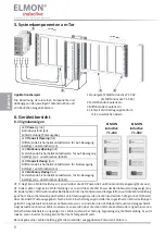
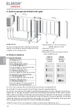
Page 16: ...tted to the gate 1 ELMON inductive 71 242 control device ELMON inductive 71 942 2 Stationary coil core 3 Travelling coil core 4 Steel cable acting as transmission medium with 2 additional wires Example of use The actual arrangement of the individual components depends on the design of the gate in question and the conditions at the installation site ELMON inductive 71 242 ELMON inductive 71 942 Eng...

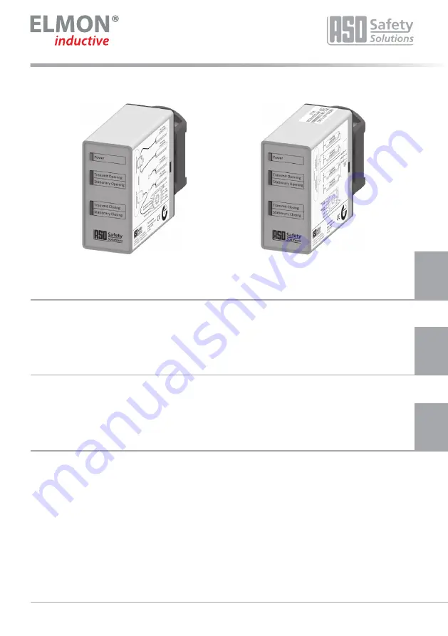
Page 17: ...d value range 2 Inductive signal transmission system error 3 Output control Open faulty 4 Output control Close faulty 5 Data transmission with microcontroller faulty 6 Testing sensor input faulty stationary safety contact edges Open Close Bottom ELMON inductive 71 942 Transmit Stationary Op Stationary Cl Pin 4 5 Pin 6 7 Pin 8 9 ELMON inductive 71 242 Pin 1 2 stationary coil core Pin 3 11 SCE leadi...

Page 18: ...no special attention is required for polarity ELMON inductive 71 942 The stationary coil core is to be connected to the Transmit slot 7 4 Connecting the stationary safety contact edges ELMON inductive 71 242 The stationary safety contact edge s on the leading pillar for the opening movement is are connected to terminal pair 3 11 ELMON inductive 71 942 The stationary safety contact edge s for the o...

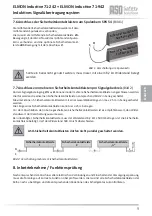
Page 19: ...ive If a channel is not used it must be connected to an 8 2 kΩ resistor The travelling safety contact edges are connected to the travelling coil core For this purpose the travelling safety contact edge CLOSING movement is connected to connection C of the travelling coil core and the optional safety contact edge OPENING movement is connected to connection O 8 Commissioning functional test The gate ...

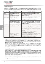
Page 20: ...incorrectly or faulty Check the connections of the corresponding safety contact edge squeezed or brittle supply lines etc Check safety contact edge s If the error is not in the wiring the function of the electronics can be tested by connecting an 8 2 kΩ resistortoallsafetycontactedgeinputsonthe ELMONinductive71 242 ELMONinductive71 942 electronic evaluation system terminals 3 10 and terminals 3 11...

Page 21: ... regulations Products can also be returned to ASO which will then dispose of them properly Stationary contact edge Travelling contact edge nominal value Rnom 8 2 kΩ 8 2 kΩ upper switching point RAO 12 kΩ 20 kΩ lower switching point RAU 5 kΩ 2 5 kΩ Terminal resistance of the safety contact edges Nominal current DC 3 A 30 V DC Nominal current AC 3 A 30 V AC Mech life time 106 actuations Relay stages...

Page 22: ...g satisfies the relevant essential health and safety requirements of the EC directives and standards listed below on account of its design and construction as does the version brought to market by us 2006 42 EC EN ISO 13849 1 2015 EN 60947 5 1 2017 2011 65 EU RoHS This declaration of conformity does not relieve the designer manufacturer of the machine from his obligation to ensure that the conform...

Page 23: ...Composants du système sur le portail 26 6 Vue d ensemble de l appareil 26 6 1 Indicateurs 26 6 2 Bornes de connexion 27 7 Raccordement de l appareil 27 7 1 Conditions 27 7 2 Alimentation 28 7 3 Raccordement du noyau de bobine stationnaire 28 7 4 Raccordement des barres palpeuses stationnaires 28 7 5 Raccordement des circuits de contrôle 28 7 6 Raccordement des barres palpeuses au noyau de bobine S...

Page 24: ...vérifier l absence de tension et le protéger contre tout réenclenchement Si une tension dangereuse alimente les contacts libres de potentiel des sorties relais il faut s assurer que cette tension est également éteinte lors des travaux sur le relais de sécurité Le relais de sécurité ne contient pas d éléments nécessitant un entretien par l utilisateur Des transfor mations ou réparations du relais d...

Page 25: ...e sécurité Le relais de sécurité contrôle constamment l actionnement ou l interruption rupture de câble de ces quatre circuits de barres palpeuses En cas d incident un des deux ordres d arrêt arrêt d ouverture ou arrêt de fer meture est attribué au circuit de barres palpeuses correspondant Afin de permettre un contrôle du courant de repos de tout le système une résistance terminale est intégrée da...

Page 26: ...impulsions émises identifie l erreur 5 Composants du système sur le portail 1 Appareil de commande ELMON inductive 71 242 ELMON inductive 71 942 2 Noyau de bobine fixe 3 Noyau de bobine mobile 4 Câble d acier comme moyen de transmission avec 2 fils supplémentaires Exemple d application La disposition des différents composants dépend de la construction spécifique du portail et des caractéristiques ...

Page 27: ...ur de transmission de signal inductif 3 Commande de sortie Open perturbée 4 Commande de sortie Close perturbée 5 Transmission de données entre microcontrôleurs perturbée 6 Erreur dans le test de l entrée du signal barres palpeuses fixes Open Close Dessous ELMON inductive 71 942 Transmit Stationary Op Stationary Cl Pin 4 5 Pin 6 7 Pin 8 9 ELMON inductive 71 242 Broches 1 2 noyau de bobine fixe Broc...

Page 28: ...bine stationnaire à la paire de bornes 1 2 la polarité n ayant aucune importance ELMON inductive 71 942 Reliez le noyau de bobine stationnaire à l emplacement Transmit 7 4 Raccordement des barres palpeuses stationnaires ELMON inductive 71 242 Raccordez la ou les barres palpeuses stati onnaires montées sur le poteau de guidage côté ouverture à la paire de bornes 3 11 ELMON inductive 71 942 Reliez l...

Page 29: ...der 500 Ω Si un canal n est pas utilisé il doit être ponté avec une résistance de 8 2 kΩ Les barres palpeuses mobiles sont reliées au noyau de bobine mobile Pour cela le mouvement de FERMETURE de la barre palpeuse mobile est raccordé au point C du noyau de bobine mobile et le mouvement d OUVERTURE en option au point O 8 Mise en service test des fonctions Après avoir effectué toutes les connexions ...

Page 30: ...ées ou défectueuses Contrôler les raccords de la barre palpeuse concernée câbles coincés fragilisés etc Contrôler la ou les barres palpeuses Si l erreur n est pas dans le câblage il est possible de vérifier le fonctionnement de l électronique en pontanttouteslesentréesdebarrepalpeusesurlesystèmeélectroniqued évaluationdel ELMONinductive 71 242 ELMONinductive 71 942 bornes3 10etbornes3 11 etsurleno...

Page 31: ...gnes locales régionales et nati onales en vigueur ASO reprend volontiers ses produits et les élimine en bonne et due forme barre palp fixe barre palp mobile valeur nominale Rnom 8 2 kΩ 8 2 kΩ valeur supérieure de com RAO 12 kΩ 20 kΩ valeur inférieure de com RAU 5 kΩ 2 5 kΩ Résistance terminale des barres palpeuses Courant nominal CC 3 A 30 V CC Courant nominal CA 3 A 30 V CA Durée de vie mécanique...

Page 32: ...isk of crushing and cutting satisfies the relevant essential health and safety requirements of the EC directives and standards listed below on account of its design and construction as does the version brought to market by us 2006 42 EC EN ISO 13849 1 2015 EN 60947 5 1 2017 2011 65 EU RoHS This declaration of conformity does not relieve the designer manufacturer of the machine from his obligation ...

Page 33: ...33 ELMON inductive 71 242 ELMON inductive 71 942 Notizen Notes Notes ...

Page 34: ...34 Induktives Signalübertragungssystem Inductive signal transmission system Système de transmission de signal inductif Notizen Notes Notes ...

Page 35: ...35 ELMON inductive 71 242 ELMON inductive 71 942 Notizen Notes Notes ...

Page 36: ...DB 04 111 Operating Manual Rev 08 Subject to technical modifications No liability can be assumed for errors or misprints This operating manual is valid for the following versions from V 1 0 to V 5 6 12 DB 04 111 Manuel d utilisation Rév 08 Sous réserve de modifications techniques Nous déclinons toute responsabilité en cas d erreurs et de fautes d impression Ce mode d emploi n est valable que pour ...

Reviews: