background image

ASM Standard Warranty 

40

332763A

ASM Standard Warranty

ASM warrants all equipment referenced in this document which is manufactured by ASM and bearing its name to be free from 
defects in material and workmanship on the date of sale to the original purchaser for use. With the exception of any special, 
extended, or limited warranty published by ASM, ASM will, for a period of twelve months from the date of sale, repair or replace 
any part of the equipment determined by ASM to be defective. This warranty applies only when the equipment is installed, 
operated and maintained in accordance with ASM’s written recommendations.

This warranty does not cover, and ASM shall not be liable for general wear and tear, or any malfunction, damage or wear caused 
by faulty installation, misapplication, abrasion, corrosion, inadequate or improper maintenance, negligence, accident, tampering, 
or substitution of non–ASM component parts. Nor shall ASM be liable for malfunction, damage or wear caused by the 
incompatibility of ASM equipment with structures, accessories, equipment or materials not supplied by ASM, or the improper 
design, manufacture, installation, operation or maintenance of structures, accessories, equipment or materials not supplied by 
ASM.

This warranty is conditioned upon the prepaid return of the equipment claimed to be defective to an authorized ASM distributor for 
verification of the claimed defect. If the claimed defect is verified, ASM will repair or replace free of charge any defective parts. The 
equipment will be returned to the original purchaser transportation prepaid. If inspection of the equipment does not disclose any 
defect in material or workmanship, repairs will be made at a reasonable charge, which charges may include the costs of parts, 
labor, and transportation.

THIS WARRANTY IS EXCLUSIVE, AND IS IN LIEU OF ANY OTHER WARRANTIES, EXPRESS OR IMPLIED, INCLUDING 
BUT NOT LIMITED TO WARRANTY OF MERCHANTABILITY OR WARRANTY OF FITNESS FOR A PARTICULAR 
PURPOSE.

ASM’s sole obligation and buyer’s sole remedy for any breach of warranty shall be as set forth above. The buyer agrees that no 
other remedy (including, but not limited to, incidental or consequential damages for lost profits, lost sales, injury to person or 
property, or any other incidental or consequential loss) shall be available.

ASM MAKES NO WARRANTY, AND DISCLAIMS ALL IMPLIED WARRANTIES OF MERCHANTABILITY AND FITNESS FOR 
A PARTICULAR PURPOSE, IN CONNECTION WITH ACCESSORIES, EQUIPMENT, MATERIALS OR COMPONENTS SOLD 
BUT NOT MANUFACTURED BY ASM. 

These items sold, but not manufactured by ASM (such as electric motors, switches, hose, 

etc.), are subject to the warranty, if any, of their manufacturer. ASM will provide purchaser with reasonable assistance in making 
any claim for breach of these warranties.

In no event will ASM be liable for indirect, incidental, special or consequential damages resulting from ASM supplying equipment 
hereunder, or the furnishing, performance, or use of any products or other goods sold hereto, whether due to a breach of contract, 
breach of warranty, the negligence of ASM, or otherwise.

FOR ASM BRAZILIAN/CANADIAN/COLUMBIAN CUSTOMERS

The Parties acknowledge that they have required that the present document, as well as all documents, notices and legal 
proceedings entered into, given or instituted pursuant hereto or relating directly or indirectly hereto, be drawn up in English.

ASM Information

For the latest information about ASM products, visit www.asmcompany.com.

TO PLACE AN ORDER, contact your ASM distributor or call 1-800-854-4025 to identify the nearest distributor.

All written and visual data contained in this document reflects the latest product information available at the time of publication. 

Graco reserves the right to make changes at any time without notice.

Original instructions. This manual contains English. MM 332763

ASM Company, 3501 N. 4th Avenue, Sioux Falls, SD 57104 

www.asmcompany.com

Revision A - 2013

Summary of Contents for 24U099

Page 1: ...s ASM L2100 Plus 230V 24U099 ASM L2100 Plus 110V 24U100 Hi Boy Models ASM L2100 Plus 230V 24U101 3300 psi 22 7 MPa 227 bar Maximum Working Pressure Important Safety Instructions Read all warnings and instructions in this manual and on the unit including the power cord Save these instructions 332763A EN Repair and Parts Electric Airless Sprayers ti22209a ti22210a Hi Boy Stand ...

Page 2: ...using Replacement 19 Spin Test 20 Fan Replacement 21 Motor Brush Replacement 22 Control Board Replacement 23 Fuse Replacement 25 Pressure Control Assembly Replacement 26 Manifold Replacement 27 Prime Valve Replacement 28 Drain Line Replacement 29 Power Cord Replacement 30 Motor Replacement 31 Wiring Diagram 32 Notes 33 Parts Stand 34 Models 24U099 and 24U100 34 Parts List Stand 35 Parts Hi Boy 36 ...

Page 3: ...repair or replacement of the cord or plug is required do not connect the grounding wire to either power terminal The wire with insulation having an outer surface that is green with or without yellow stripes is the grounding wire Check with a qualified electrician or serviceman when the grounding instructions are not completely under stood or when in doubt as to whether the product is properly grou...

Page 4: ...a Sheets MSDS and container labels provided with the paints and solvents Follow the paint and solvents manufacturer s safety instructions Fire extinguisher equipment shall be present and working Sprayer generates sparks When flammable liquid is used in or near the sprayer or for flushing or cleaning keep sprayer at least 20 feet 6 m away from explosive vapors SKIN INJECTION HAZARD High pressure sp...

Page 5: ...pment must be grounded Improper grounding setup or usage of the system can cause elec tric shock Turn off and disconnect power cord before servicing equipment Connect only to grounded electrical outlets Use only 3 wire extension cords Ensure ground prongs are intact on power and extension cords Do not expose to rain Store indoors PRESSURIZED ALUMINUM PARTS HAZARD Use of fluids that are incompatibl...

Page 6: ...QUIPMENT Wear appropriate protective equipment when in the work area to help prevent serious injury including eye injury hearing loss inhalation of toxic fumes and burns This protective equipment includes but is not limited to Protective eyewear and hearing protection Respirators protective clothing and gloves as recommended by the fluid and solvent manufacturer CALIFORNIA PROPOSITION 65 This prod...

Page 7: ... Hi Boy Models D P L K C N B A S F R H E J M G ti22418a T A ON OFF Switch B Pressure Gauge C Prime Valve D Model Serial Tag E Guard F Tip G Power Cord H Gun J Fluid Hose K Trigger Lock L Drain Hose M Suction Hose N Pump P Pail Hook R Fluid Outlet S Filter T Pressure Control ...

Page 8: ...ication Stand Models A ti22419a E G F J K H L N R S B C D M T A ON OFF Switch B Pressure Control C Pressure Gauge D Prime Valve E Model Serial Tag F Guard G Tip H Gun J Fluid Hose K Trigger Lock L Drain Hose M Suction Hose N Pump R Fluid Outlet S Filter T Power Cord ...

Page 9: ... 7 Turn power switch OFF if unit is being shut down or will be left unattended If you suspect the spray tip or hose is clogged or that pressure has not been fully relieved after following the steps above VERY SLOWLY loosen tip guard retaining nut or hose end coupling to relieve pressure gradually then loosen completely Clear hose or tip obstruction This equipment stays pressurized until pressure i...

Page 10: ...un dispense valve firmly to the side of a grounded metal pail then trigger the gun valve Power Requirements 100 120V units require 100 120 VAC 50 60 Hz 11A 1 phase 230V units require 230 VAC 50 60 HZ 7 5A 1 phase The sprayer cord includes a grounding wire with an appropriate grounding contact The plug must be plugged into an outlet that is properly installed and grounded in accordance with all loc...

Page 11: ...a nonconductive surface such as paper or cardboard which interrupts grounding continuity Grounding a metal pail connect a ground wire to the pail by clamping one end to pail and other end to a true earth ground such as a water pipe To maintain grounding continuity when flushing or relieving pressure hold metal part of spray gun firmly to side of a grounded metal pail Then trigger gun ti5851a ti531...

Page 12: ...er removed NOTICE Do not operate the sprayer without the motor shroud in place Replace if damaged Motor shroud directs cool ing air around motor to prevent overheating Operating the sprayer without the motor shroud in place will result in damage to the sprayer To reduce risk of serious injury including electric shock Do not touch moving or electric parts with fingers or tools while testing repair ...

Page 13: ...Mechanical 1 Pump frozen or hardened paint Thaw sprayer if water or water based paint has frozen in sprayer Place sprayer in warm area to thaw Do not start sprayer until thawed completely If paint hardened dried in sprayer replace pump packings See page 17 Displacement Pump Replacement 2 Displacement pump connecting rod pin Pin must be completely pushed into con necting rod and retaining spring mu...

Page 14: ...ng or loose brush lead connections Install brush cap or replace brushes if leads are damaged See page 22 Motor Brush Replacement 8 230V models only Capacitor board for damaged capacitors burn marks or a cracked red MOV Replace capacitor board after completing motor inspection See page 23 Control Board Replacement 9 230V models only Capacitors with a multimeter Disconnect capacitor con nectors D E ...

Page 15: ...ten sion cord See page 10 Grounding and Electric Requirements 7 Leads from motor to circuit board for damaged or loose wire connectors Inspect wiring insulation and terminals for signs of overheating Be sure male terminal pins are centered and firmly connected to female terminals Replace any loose terminals or damaged wiring Securely reconnect terminals 8 Worn motor brushes which must be 1 4 in 6 ...

Page 16: ...ousing Replacement Motor is hot and runs intermittently 1 Be sure ambient temperature where sprayer is located is not more than 115 F 46 C and sprayer is not located in direct sun Move sprayer to shaded cooler area if possible 2 Motor has burned windings indicated by removing positive red brush and see ing burned adjacent commutator bars Replace motor See page 31 Motor Replacement 3 Tightness of p...

Page 17: ...e B Loosen two screws 30 Push cover 44 up and remove from sprayer 3 Loosen nut 95 and remove suction hose 35 Loosen nut B and remove the high pressure hose 14 4 Cycle pump until pin 8 is in position to be removed 5 Disconnect power cord from outlet 6 Push up retaining spring 7a Push out pump pin 8 7 Loosen pump jam nut 10 Unscrew and remove pump 9 Style A TI A 30 44 11 10 ti9138a Style B 14 B 95 3...

Page 18: ...ately 75 ft lb 102 N m 8 Install suction tube 35 and coupled hose 14 Tighten nuts 95 and B 9 Fill packing nut with ASM Packing Seal until fluid flows onto top of seal 10 Style A rotate cover 44 back over screws Tighten two screws 30 Style B replace cover 44 over screws Push cover down into place Tighten two screws 30 If pump pin works loose parts could break off due to force of pumping action Part...

Page 19: ...al coat of grease to gears and needle bearing surfaces Install thrust bearing 4 and gears 2 and 3 in motor front endbell 2 Push drive housing 5 into motor front endbell Insert gear crank 3 through hole in connecting rod 7 3 Install four screws 6 4 Install cover 32 with two screws 30 5 Install pump 9 Displacement Pump Replace ment page 17 NOTICE Gear cluster may stay engaged in motor front endbell ...

Page 20: ...lete stop there are no electrical shorts If motor does not spin freely armature is shorted Replace Motor page 31 Armature Brushes and Motor Wiring Open Circuit Test Continuity 1 Connect red and black motor leads with test lead Turn motor fan by hand at about two revolutions per second 2 If uneven or no resistance check for missing brush caps broken brush springs brush leads and worn brushes Repair...

Page 21: ...cord from outlet 2 Remove two screws 30 and shroud 29 3 Remove spring clip 1b on back of motor 4 Pull off fan 1a Installation 1 Slide new fan 1a in place on back of motor Be sure blades of fan face motor as shown 2 Install spring clip 1b 3 Install shroud 29 and two screws 30 1b 1a 30 29 ti12422a ...

Page 22: ...e all new parts included in brush kit Do not reuse old parts if new replacement parts are provided 1 Install new brushes B in motor with wires facing toward front of motor Install positive red brush lead in top of motor and negative black brush lead in the side of motor 2 Push each cap A into place over brush Orient each cap with the two projections on either side of the brush lead You will hear a...

Page 23: ...crews 30 securing control board to housing two are located on the front and one on the back next to the power cord 7 230V models only Remove screw securing capacitor board and bracket to housing 8 Pull control board out slightly and then slide control board back and off of frame NOTE Make sure power cord is free and not wrapped around cord wrap 9 Remove grommet and wires from strain relief NOTE Gr...

Page 24: ...stall capacitor board with screw and bracket 33a Torque to 35 40 in lb 6 Connect motor connector B and pressure control assembly connector A 230V models only a Attach red and black wires H F from control board 33 to capacitor board 33a b Attach red and black wires D E from capacitor board 33a to control board 33 7 Install shroud 29 with screws 30 ti6122a 33 Grommet Strain Relief ti6143a 230V 120V ...

Page 25: ...t page 20 A locked or frozen pump Correct defective condition before replacing fuse Removal 1 Relieve pressure page 9 Disconnect power cord from outlet 2 Remove two screws 30 and shroud 29 3 Remove fuse from control board Installation 1 Install new fuse on control board 2 Install shroud 29 and two screws 30 Replaceable Fuse ti9134b ...

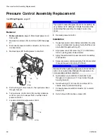
Page 26: ...the wires are routed through bushing 21 2 Align pressure control wire cap 17 on fluid mani fold so opening faces toward motor 3 Apply thread sealant to pressure control assembly 16 threads 4 Screw pressure control assembly 16 into manifold 15 and torque to 150 in lb 17 0 N m 5 Guide wires around bottom of knob and route through slot in wire cap 17 Feed wires through housing hole K 6 Insert bushing...

Page 27: ...tch from manifold See Pressure Control Assembly Replacement page 26 9 Remove two screws 6 to disconnect manifold 15 from housing Installation 1 Position manifold 15 on sprayer frame 2 Replace screws 6 and torque to 150 in lb 17 N m 3 If removed install pressure control assembly See Pressure Control Assembly Replacement page 26 4 Feed pressure switch wires through hole in housing K 5 Insert bushing...

Page 28: ... 15 5 Remove valve seat 23b and seat gasket 23a from inside of filter manifold or end of prime valve Installation 1 Install new seat gasket 23a and valve seat 23b on end of prime valve 2 Thread prime valve 23 into filter manifold 15 Torque to 120 to 130 in lb 3 Push valve base 24 over prime valve 23 and then valve prime handle 25 over valve base 4 Install new pin 26 in prime valve handle If neces ...

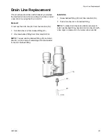
Page 29: ...0 from barbed fitting 20 2 Unscrew barbed fitting from filter manifold 15 NOTE To reuse existing barbed fitting 20 and drain line 40 cut and remove remaining drain line material from end of barbed fitting Installation 1 Screw barbed fitting 20 into filter manifold 15 2 Push drain line 40 onto barbed fitting NOTE To make drain line more pliable and easier to install over barbed fitting heat end of ...

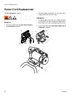
Page 30: ...2 Remove green ground screw 31 and disconnect green ground wire G from frame Installation 1 Connect green ground wire G to frame with green ground screw 31 Be sure green ground wire ter minal faces up or wires could get caught in shroud 2 Install control board Control Board Replacement Installation page 23 ti6143a 230V 120V 33 C A B B A H D E F C 33 33a G 31 ...

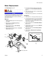
Page 31: ...new motor on frame 45 with four screws 6 2 Connect green ground wire G to frame with green ground screw 31 Be sure green ground wire ter minal faces up or wires could get caught in shroud See illustration page 25 3 Install control board 33 Control Board Replace ment page 23 4 Install manifold 15 with two screws 6 Manifold Replacement page 27 5 Install drive housing 5 Drive Housing Replace ment pag...

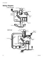
Page 32: ...22267a Black Red From Motor 2X Yellow Pressure Control Assembly White Black Replaceable Fuse ON OFF Switch Capacitor Power Plug From Motor 2X Yellow Black Red Pressure Control Assembly ON OFF Switch Green Green Blue Brown Black E Red D Power Plug Red H Black F Red MOV Capacitors ...

Page 33: ...Notes 332763A 33 Notes ...

Page 34: ...9 and 24U100 25 1b Ref 34 5 6 32 63 30 30 6 44 7 8 7a 10 64 51 50 33a 3 4 2 1 14 13 9 40 41 12 12 11 35 35 43 37 6 45 46 27 28 67 34 47 48 40 20 74 75 13 13 22 105 18 16 104 103 106 30 15 17 14 6 6 23 24 23a b 26 30 29 77 31 1a 21 30 33 36 ti22426a ...

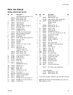
Page 35: ... 4 in x 50 ft 1 28 289316 GUN 500 2 finger ASM 1 29 277420 SHIELD motor 1 30 117501 SCREW mach slot hex wash hd 9 31 115498 SCREW mach slot hex wash hd 1 32 276883 COVER front 1 33 BOARD control 255483 Model 24U100 120V 1 16X295 Model 24U099 230V includes 33a 1 33a 24R905 CAPACITOR BOARD 230V Model 24U099 34 CORD 253368 Model 24U100 UK 1 253369 Model 24U099 CEE 7 7 1 35 246386 HOSE suction 1 36 18...

Page 36: ...odel 24U101 24 13 31 Ref 34 6 13 45 101 102 1 5 29 44 15 103 105 104 106 17 16 18 23 20 25 26 2 3 4 7 8 9 10 13 35 12 7a 95 30 6 32 30 21 33 30 30 98 6 40 41 110 14 46 63 36 50 64 75 37 30 22 74 34 28 67 27 1b 1a 33a 23a b 11 38 77 ti22434a ...

Page 37: ...in x 50 ft 1 28 289316 GUN 500 2 finger ASM 1 29 15M656 SHIELD motor 1 30 117501 SCREW mach slot hex wash hd 9 31 115498 SCREW mach slot hex wash hd 1 32 276883 COVER front 1 33 16X295 BOARD control 230V includes 33a 1 33a 24R905 CAPACITOR BOARD 230V 1 34 253369 CORD CEE 7 7 1 35 15J801 TUBE suction intake 1 36 189930 LABEL caution 1 37 235004 STRAINER 3 4 16 unf 1 38 15B652 WASHER suction 1 40 15...

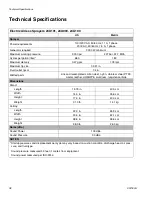
Page 38: ... 4 in Wetted parts zinc and nickel plated carbon steel nylon stainless steel PTFE Acetal leather UHMWPE aluminum tungsten carbide Dimensions Stand Length 15 75 in 40 0 cm Width 14 0 in 35 6 cm Height 17 0 in 43 0 cm Weight 31 0 lb 14 1 kg Hi Boy Length 22 0 in 55 9 cm Width 20 5 in 52 1 cm Height 38 8 in 98 6 cm Weight 58 0 lb 26 3 kg Noise dBa Sound Power 100 dBa Sound Pressure 90 dBa NOTES Start...

Page 39: ...Notes 332763A 39 Notes ...

Page 40: ...OR IMPLIED INCLUDING BUT NOT LIMITED TO WARRANTY OF MERCHANTABILITY OR WARRANTY OF FITNESS FOR A PARTICULAR PURPOSE ASM s sole obligation and buyer s sole remedy for any breach of warranty shall be as set forth above The buyer agrees that no other remedy including but not limited to incidental or consequential damages for lost profits lost sales injury to person or property or any other incidental...

Reviews: