


Page 6
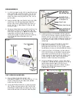
Figure 17
Hex
Nut
White
Alignment
Mark
Motor
Connector
Harness
Round
Nut
#2 Phillips screwdriver to remove the five screws (PN:
510406), lock washers (PN: 510010), and flat washers
(PN: 510587) that attach PCB Assembly to the nylon
standoffs on Chassis. Remove PCB Assembly and set
aside for reuse later (see Fig 16) (
NOTE:
The PCB
Assembly is a non-serviceable component of the AEU-
7000L/7000E System. If not functioning properly,
replace with a new Assembly.) Use a ¼" wrench to
remove the five nylon standoffs (PN: 510626) from
Chassis. When reassembling the PCB Assembly, pull
motor wires and 48V DC wires forward and secure
them to the Chassis standoff with a tie wrap so that
the single wires cannot touch the back of the Chassis.
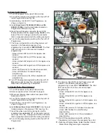
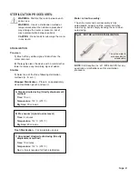
20.
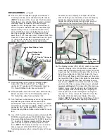
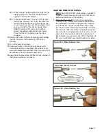
Locate Cable Clamp (PN: 510410) on Chassis
adjacent to Motor Connector (see Fig. 17). Use a
5/16" wrench to remove kep nut (PN: 510006).
Remove Clamp.
21.
Remove screws (PN: 510406) and lock washers (PN:
510419) from slotted holes in bottom of Chassis that
connect Motor Connector subassembly to Chassis
(see Fig. 8). Use a ¾" open-ended wrench to loosen
hex nut (PN: 461970) on the inboard side of Motor
Connector Bracket (PN: 461546), which attaches
Motor Harness Assembly to Bracket (see Fig. 17).
Remove round connector nut (PN: 461969) from
outboard side of Bracket. Remove Motor Harness
Assembly (PN: 461546) from Bracket. Set Motor
Harness and Connector Bracket aside for reassembly
later. (
NOTE:
When reassembling Motor Connector
subassembly, insert Motor Connector from inboard
side of Bracket, outwards through Bracket cutout. Align
the flats on Connector barrel with flats on cutout and
ensure white alignment mark on Connector is position-
ed at the top. Apply a drop of white glue (PN: 490142)
to the Connector threads before installing round and
hex nuts. From outboard side of Bracket, thread round
nut up the barrel of Connector by hand until the white
alignment mark becomes visible, with approximately
one thread showing on face of Connector. Tighten hex
nut on the other side of the Bracket to snug Harness
Assembly up against Bracket.)
22.
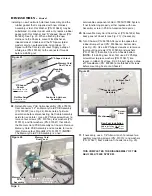
Use a 5/16" wrench to remove three nylon nuts (PN:
510745) and rubber grommets (PN: 870185) that
attach Dynamometer subassembly to Chassis (see
Fig. 18). Remove subassembly. Remove three nylon
spacers (PN: 510163) and Insulator (PN: 461979)
from underneath subassembly. Use a 5/64" Allen
wrench to loosen setscrew (PN: 510278) that secures
the Dynamometer Adapter (PN: 461540) to
Dynamometer shaft. Remove Adapter and set aside
for reassembly later. (
NOTE:
When reassembling
Adapter onto Dynamometer shaft, apply a drop of
Threadlocker (PN: 490053) to setscrew, then torque
the setscrew to 8-10 in.lb.) Use a #1 Phillips
screwdriver to remove four screws (PN: 510627) that
attach the Dynamometer to the Dynamometer Bracket
(PN: 461551). Remove Dynamometer from Bracket.
(
NOTE:
The Dynamometer is a non-serviceable
Figure 16
Nylon Standoff (X5)
PCB Assy
Figure 18
Rubber
Grommet
(X3)
Dynamometer
Dynamometer
Adapter
Nylon Spacer
(X3)
Dynamometer
Subassembly
Setscrew
DISASSEMBLY -
Cont’d
Cable
Clamp