


Page 5
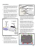
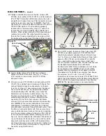
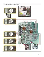
Figure 14
Bezels
Locking Tabs
16.
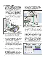
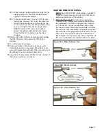
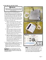
The Control Panel Overlay Assembly (7000L PN:
420860; 7000E PN: 420584) is attached to Top Cover
with an adhesive backing (see Fig. 13a). Removal of
the Overlay is not recommend-ed unless absolutely
necessary. If removal is required, carefully peel the
Overlay out of recess in Cover and permanently
discard entire Overlay Assembly. (
NOTE: Do not
reuse an old Overlay Assembly
- a detached
Overlay should always be replaced with a brand new
Assembly.) To reinstall new Overlay: 1) Insert flex
cable pigtail through the slotted hole in the Top Cover;
2) Remove liner from adhesive backing on new
Assembly; 3) Carefully center new Assembly in recess
in Top Cover; and, 4) Press down evenly on Assembly
until firmly adhered to Cover. On the underside of the
Cover, tape a loop in the Control Panel Flex Cable (do
not crease) using 2.0” of Kapton Tape (PN: 490088).
See Fig. 13b.
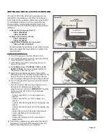
17.
From the inboard side of Cover, use fingers (or pliers)
to pinch together the locking tabs of Dynamometer
Bezel (PN: 461538) and Motor Connector Bezel (PN:
461545) (see Fig. 14). Push each Bezel outward
through its respective hole in Cover. Set Bezels aside
for reuse later. (
NOTE:
When remounting Bezels,
ensure that locking tabs fully snap over edges of
holes, into grooves provided on inside of Cover.)
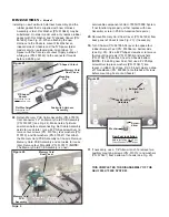
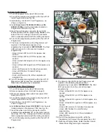
18.
Cut and remove the cable tie surrounding the cable
bundle on right-hand side of PCB Assembly (see Fig.
15). Detach Pump Assembly cable connector at 'J1'
("Pump") location on PCB Assembly. Make note of
pin/wire alignments of connectors before disconnect-
ing from PCB. Use a #2 Phillips screwdriver to
remove two Pump Assembly mounting screws (PN:
510406) and lock washers (PN: 510419) from bottom
of Chassis (see Fig. 8). Remove Pump Assembly
(PN: 330471). Remove the two Isolation Pads (PN:
461995) underneath the Pump. (
NOTE:
The Pump
Assembly is a non-serviceable component of AEU-
7000L/7000E System. If not functioning properly,
either replace with new Assembly or return Pump to
Aseptico for repairs.)
CHASSIS DISASSEMBLY:
19. Disconnect all cable and wire connectors from PCB
Assembly (7000L PN: 330575/7000E PN: 330514).
Make note of each cable’s routing and connector/pin
orientation before disconnecting from PCB (see Fig.
15). Cut and remove cable ties as necessary. Use a
Figure 15
Pump
Assy
Pump Cable Connector
Pump Assy Mtg. Hardware (X2)
Cable
Tie
Slot
In
Cover
Overlay
Flex Cable
Pigtail
Control Panel
Overlay
Assembly
Figure 13a
Figure 13b
Kapton
Tape
Loop