


Page 26
1
FINAL
ASSY
AEU-7000E
120330
1
2
LINECORD
WHT
HOSPT
GRDE
5-15PH6C
840079
1
3
MOT
OR/CABLE
ASSY
AE-230M-40
1
4
FINAL
ASSY
AE-70V2
FOOT
CONTROL
V
AR
120391-01
1
5
HOLDER
IRRIGANT
BAG
461541
1
6
ADAPTER
HANDPIECE
461558
1
7
HANDPIECE
CRADLE
461561-01
1
8
BRACKET
CRADLE
461562
1
9
M/S
STNLS
PHDPHL
6-32
X
3/8
510406
18
10
W
ASHER
INT
ST
AR
S/S
#6
510419
13
11
LABEL
SERIAL
NUMBER
AEU-7000L/7000E
420556-02
1
12
M/S
6/32
X
2-1/2
PNHD
PH
SS
510643
4
13
CABLE
RIBBON
SOC
TO
SOC
14
POS
870300
1
14
VACUUM
FLUORESCENT
DISPLA
Y
ASSY
330503
1
15
NUT
HEX
4-40
SML
PTN
PL
TD
510005
2
16
W
ASHER
SPLIT
PL
TD
#4
510004
2
17
STUD
PRESS
510625
2
18
DISPLA
Y
FIL
TER
461548
1
19
GASKET
DISPLA
Y
461549
1
20
OVERLA
Y
MEMBRANE
CONTROL
PNL
420584
1
21
BEZEL
DYNAMOMETER
461538
1
22
BEZEL
MOT
OR
CONNECT
OR
461545
1
23
SP
ACER
COVER
AEU-7000
461560
4
24
TAPE
KAPT
ON
1/4
INCH
WIDE
ROLL
490088
2"
25
TOP
COVER
461547
1
26
PUMP
ASSY
PERIST
AL
TIC
330471
1
ISOLA
TION
PAD
PUMP
BRACKET
AEU-7000
461995
2
27
CHASSIS
ASSY
AEU-7000
330469
1
28
PCB
ASSY
POWER
&
STEPPR
BRD
CMPL
330514
1
W
ASHER
SPLIT
PL
TD
#6
510010
13
W
ASHER
STNLS
NAS
620-C6
.143IDx.267OD
510587
13
29
ST
ANDOFF
1/4
HEX
#6
X
1-7/8
NYL
510626
5
30
NUT
KEPS
PL
TD
6-32
510006
3
31
W
ASHER
EXT
ST
AR
PL
TD
#6
510007
2
32
MOT
OR
HARNESS
ASSY
875073
1
33
NUT
MOT
OR
CONNECT
OR
CMPL
461969
1
NUT
HEX
MOT
OR
CONNECT
OR
461970
1
34
BRACKET
CONNECT
OR
461546
1
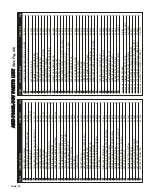
ITEM
DESCRIPTION
PAR
T
NO.
Qty
1
2
3
4
5
6
7
8
9
10
11
12
13
14
15
17
16
18
19
20
21
22
23
26
24
25
27
28
30
29
31
32
33
ITEM
DESCRIPTION
PAR
T
NO.
Qty
34
35
36
37
CLAMP
CABLE
NYLON
5/16
DIA
X
.203
HOLE
510410
1
35
BRACKET
DYNAMOMETER
AEU-7000
461551
1
36
NUT
NYLON
LOCK
6-32
510745
3
38
GROMMET
1/4"
NEOPREME
BLK
870185
3
39
SP
ACER
NYL
1/4RND
X
1/4LX
#6
510163
3
40
ADAPTER
DYNAMOMETER
461540
1
41
SETSCREW
8-32X1/8
S/S
CUP
POIN
510278
1
42
DYNAMOMETER
ASSEMBY
330481
1
43
M/S
PHD
PHL
M3X.5X6
SEMS
W/WSR
510627
4
INSULA
TOR
DYNAMOMETER
461979
1
44
CABLE
ASSY
DC
48
VOL
T
875076
1
45
CABLE
ASSY
AC
LINE
IN
875077
1
46
POWER
SUPPL
Y
48VDC
2.9A
INPUT
100-240V
AC
8401
13
1
M/S
PANSL
T
NYLON
6-32
X
5/16
510746
8
47
ST
ANDOFF
NYLON
6-32
X
7/16
L
X
1/4
HEX
510747
8
47
CABLE
ASSY
MEMOR
Y
PCB
875078
1
48
PCB
ASSY
MEMOR
Y
CARD
330507
1
49
CABLE
ASSY
AC
EAR
TH
875075
1
CABLE
ASSY
GROUND
8751
12
1
50
FUSEDRA
WER
2
POLE
840060
1
51
FUSE
5X20MM
SLO-BLO
1.60A
830040
2
TAPE
KAPLON
1
INCH
WIDE
ROLL
490144
1"
52
POWER
INLET
FUSED
10
AMP
W/LINE
FIL
TER
840086
1
53
CABLE
ASSY
PROGRAMMING
875057-01
2
54
FOOTSWITCH
HARNESS
ASSY
875074
1
56
W
ASHER
FLA
T
.625
ID
.875
OD
NYL
510648
1
57
DUST
COVER
FLASH
CARD
461606
1
58
FOOT
BUMPER
RECESS
.75
X
.25
850066
4
59
C/S
BTNSOC
STNLS
10-32X1/2
510312
2
60
W
ASHER
INT
ST
AR
S/S
#10
510421
2
61
CHASSIS
BASE
AEU-7000
CMPL
461955-08
1
NOT
SHOWN
TUBING
SET
BAG
AE-23
1
NOT
SHOWN
TUBING
SET
PUMP
SECTION
AE-23-PUMP
1
NOT
SHOWN
MEMOR
Y
CARD
ASSY
AEU-7000E
MC-7000E
1
NOT
SHOWN
SOFTW
ARE
AEU-7000
MOT
OR
DRIVER
890021
1
NOT
SHOWN
SOFTW
ARE
AEU-7000
MASTER
CODE-POR
T
1
890022
1
NOT
SHOWN
SOFTW
ARE
AEU-7000
SLA
VE
CODE-POR
T
2
890023
1
NOT
SHOWN
FOOTSWITCH
ON/OFF
4
PIN
MALE
AE-7PM
1
45
46
47
48
49
50
51
52
53
57
56
54
55
58
60
59
61
62
63
64
66
65
67
41
42
43
44
68
69
39
40
38
AE
U-
70
00
E-
70
V
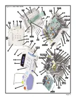
PA
RTS
L
IS
T
(See
Fig.
44)