Ascon tecnologic K48 Engineering Manual Download Page 14

Ascon Tecnologic - K Series - ENGINEERING MANUAL - Vr. 9.0

 PAG. 14

[59] int - Integral time

Available: 

When [52] cont = PID and [55] SELF = no.

Range: 

OFF = Integral action excluded;
1... 9999 seconds;
inF= Integral action excluded.

Note: 

Auto-tune functions calculate this value.

[60] dEr - Derivative time

Available: 

When [52] cont = PID and [55] SELF = no.

Range: 

oFF = Derivative action excluded;
1... 9999 seconds.

Note: 

Auto-tune functions calculate this value.

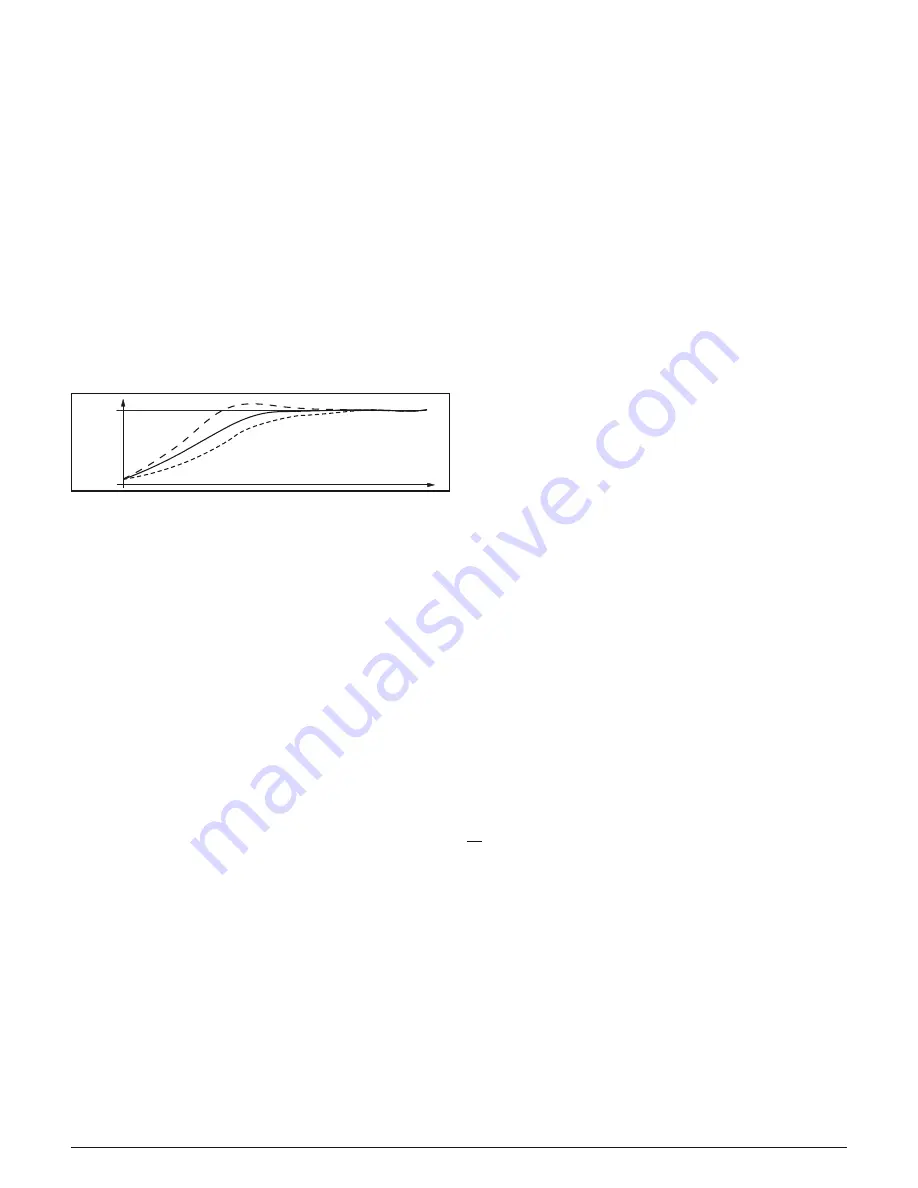
[61] Fuoc - Fuzzy overshoot control

This parameter reduces the overshoot usually present at 
instrument start up or after a set point change and it will be 
active only in this two cases.
Setting a value between 0.00 and 1.00 it is possible to slow 
down the instrument action during set point approach.
Setting 

Fuoc = 1

 this function is disabled.

PV

SP

time

2

1

3

Available: 

When [49] cont = PID and [52] SELF = no.

Range: 

0... 2.00.

Note: 

Fast auto-tune calculates the Fuoc parameter while 
the oscillating-tune sets it equal to 0.5.

[62] H.Act - Heating output (H.rEG) actuator

This parameter sets the minimum cycle time of the heating 
output.
It aims to respect the minimum cycle time of a specific 
actuator in order to ensure a long actuator life. 

Available: 

When at least one output is programmed in order 
to be the heating output (H.rEG), [52] cont = PID 
and [55] SELF = no.

Range: 

SSr =  Solid state relay output;
rELY =  Relay or contactor;
SLou=  Slow actuator (e.g. burners).

Note: 

Setting:

• 

SSr no limit is applied to the auto-tune calculation and 
[63] tcrH is pre-set equal to 1 second.

• 

rELY the limit applied to the auto-tune calculation is equal 
to 20 seconds and [63] tcrH is pre-set equal to 20 seconds.

• 

SLou the limit applied to the auto-tune calculation is equal 
to 40 seconds and [63] tcrH is pre-set equal to 40 seconds.

[63] tcrH - Cycle time of the heating output

Available: 

When at least one output is programmed in order 
to be the heating output (H.rEG), [52] cont = PID 
and [55] SELF = no.

Range:  • 

When [62] H.Act = SSr: 1.0... 130.0 seconds;

• 

When [62] H.Act =  reLY: 20.0... 130.0 seconds;

• 

When [62] H.Act = SLou: 40.0... 130.0 seconds.

Note: 

Auto-tune functions calculate this value but, when 
necessary, it is possible to set it manually.

[64] PrAt  - Power ratio between heating and 

cooling action (relative cooling gain)

The instrument uses the same PID parameter set for heat 
and for cool action but the efficiency of the two actions are 
usually different.
This parameter allows to define the ratio between the 
efficiency of the heating system and the efficiency of the 
cooling one.
An example will help us tu explain you the philosophy.
Consider one loop of a plastic extruder.
The working temperature is equal to 250°C.
When you want to increase the temperature from 250 to 
270°C (

Δ

20°C) using 100% of the heating power (resistor), 

you will need 60 seconds.
On the contrary, when you want to decrease the temperature 
from 250 to 230°C (

Δ

20°C) using 100% of the cooling power 

(fan), you will need  20 seconds only.
In our example the ratio is equal to 60/20 = 3 ([60] PrAt = 3) 
and says that the efficiency of the cooling system is 3 times 
more efficient than the heating one.

Available: 

When two control action are programmed (H.rEG 
and c.rEG) and [52] cont = PID and [55] SELF = no.

Range: 

0.01... 99.99.

Note: 

Auto-tune functions calculate this value.

[65] c.Act - Cooling output (C.rEG) actuator

Available: 

When at least one output is e programmed in 
order to be the cooling output (c.rEG),  
[52] cont = PID and [55] SELF = no.

Range: 

SSr = 

Solid state relay output;

rELY =  Relay or contactor;
SLou =  Slow actuator (e.g. compressors).

Note: 

For more details see [62] h.Act parameter.

[66] tcrc - Cycle time of the cooling output

Available: 

When at least one output is programmed in order 
to be the cooling output (c.rEG),  
[52] cont = PID and [55] SELF = no.

Range:  • 

When [65] c.Act = SSr: 1.0... 130.0 s;

• 

When [65] c.Act = reLY: 20.0... 130.0 s;

• 

When [65] c.Act = SLou: 40.0... 130.0 s.

Note: 

Auto-tune functions calculate this value but, when 
necessary, it is possible to set it manually

[67] rS - Manual reset (integral pre-load)

rS

 allows to drastically reduces the undershoot due to a 

hot restart.  When your process is steady, the instrument 
operates with a steady power output (e.g. 30%).
If a short power down occurs, the process restarts with a 
process variable close to the set point while the instrument 
starts with an integral action equal to zero. 
Setting a manual reset equal to the average power output 
(in our example 30%) the instrument will start with a power 
output equal to the value it will use at steady state (instead 
of zero) and the undershoot will become very little (in theory 
equal to zero).

Available: 

When [52] cont  = PID and [55] SELF = no.

Range: 

-100.0... 100.0%.

Summary of Contents for K48

Page 1: ...n 5 The ambient temperature is in accordance with the operative temperature 0 50 C 6 The relative humidity is in accordance with the instrument specifications 20 85 The instrument can be mounted on pa...

Page 2: ...ut circuit Current injection 25 A Line resistance Not compensated 2 2 5 V and mV Input mV V _ _ 2 1 Input impedance 1 M Accuracy 0 5 of Span or 1 dgt 25 C 2 2 6 mA Input 0 4 20 mA input wiring for pas...

Page 3: ...te This output is not isolated A double or reinforced isolation between instrument output and power supply must be assured by the external solid state relay 2 3 3 Output 3 OP3 Relay Output 6 5 NO C Co...

Page 4: ...splay updating time 500 ms Sampling time 130 ms Resolution 30000 counts Total accuracy 0 5 F S V 1 digit 25 C of room temperature Electromagnetic compatibility and safety requirements Compliance Direc...

Page 5: ...rol output is equal to 0 and can be manually modified by and buttons Stand by mode St bY The display alternately shows the measured value and the message St bY or od The instrument does not perform an...

Page 6: ...complete list of the default parameter is available in Appendix A 5 7 All parameters configuration In the following pages we will describe all the parameters of the instrument However the instrument...

Page 7: ...instrument will use the Zero value 2 When ON OFF control is programmed and an out of range is detected the instrument will perform the safety output value using a fixed cycle time equal to 20 seconds...

Page 8: ...tion is cyclic SP1 SP2 SP3 SP4 out Group Output parameters 12 o1F Out 1 function Available Always Range nonE Output not used With this setting Out 1 status can be driven directly from serial link H rE...

Page 9: ...Power failure indicator bo PF Out of range burn out and Power Failure indicator diF1 The output repeates the digital input 1 status diF2 The output repeates the digital input 2 status St By Stand By s...

Page 10: ...n other words when the initial alarm condition disappears PWR ON AL1 PV time off off Ab1 1 Ab1 0 off off ON ON ON 2 A Latched alarm manual reset is an alarm that remains active even if the conditions...

Page 11: ...s programmed as control output nonE Alarm not used LoAb Absolute low alarm HiAb Absolute high alarm LHAb Absolute band alarm SE br Sensor break Note The relative alarm are relative to the current set...

Page 12: ...for a time longer than 46 AL3d time but the reset is immediate 47 AL3o Alarm 3 enabling during Stand by mode and out of range indications Available When 40 AL3t ia different from nonE Range 0 Never 1...

Page 13: ...if the set point is close to the ambient temperature 2 The fast type auto tune is suitable when The process is very slow and you want to be operative in a short time When an high overshoot is not acc...

Page 14: ...oling gain The instrument uses the same PID parameter set for heat and for cool action but the efficiency of the two actions are usually different This parameter allows to define the ratio between the...

Page 15: ...imit is applied to the cooling action the soft start function will be aborted when the measured value is lower than or equal to SS tH parameter SP Group Set point parameters The SP group will be avail...

Page 16: ...lers The Slave zones use it as a set point trim The first zone is the master zone and it uses a set point equal to 210 C The second zone has a local set point equal to 45 C The third zone has a local...

Page 17: ...tatus of two events An event can drive an output and make an action during one or more specific program steps Some additional parameters allow to define the time scale the automatic RUN conditions and...

Page 18: ...t 2 00 00 off off off off 10 00 on off off off 01 00 off on off off 11 00 on on off off Display Ramp Soak Event 1 Event 2 Event 1 Event 2 00 10 off off on off 10 10 on off on off 01 10 off on on off 1...

Page 19: ...1 parameter 113 Pr St Program status Available When 89 Pr F is different from nonE Range run Program Run HoLd Program Hold rES Program reset Note This parameter allows to manage program execution by a...

Page 20: ...is equal to in finite the limit is always active and it can be used also when ON OFF control is selected 118 AdE Bargraph deviation Available Always Range oFF Bargraph not used 1 9999In engineering u...

Page 21: ...shold not used 1 999 days 1 999 hours CAL Group User calibration group This function allows to calibrate the complete measuring chain and to compensate the errors due to Sensor location Sensor class s...

Page 22: ...L1 AL2 A 6 AL2 Pb A 7 Pb Int A 8 Int dEr A 9 dEr Aut r A 10 Aut r Now proceed as follows 1 Push the button for more than 3 seconds 2 The display alternately shows PASS and 0 3 By and buttons set a pas...

Page 23: ...and the parameter modification procedure is closed When you desire to remove the time out e g for the first configuration of an instrument you can use a password equal to 1000 plus the programmed pas...

Page 24: ...preceded by a P letter P84 3 4 Push button again When the wattmeter function is running the display shows U followed by the measured energy Note The energy calculation will be in accordance with the 1...

Page 25: ...set manual modes during self tune execution the self tune function will be aborted 4 During manual mode all functions not related with the control wattmeter indipendent timer worked time etc continue...

Page 26: ...ment to our company The faulty product must be shipped to Ascon Tecnologic with a detailed description of the faults found without any fees or charge for Ascon Tecnologic except in the event of altern...

Page 27: ...and Under our C 0 9 oPE Safety output value 0 100 100 0 C 0 10 diF1 Digital input 1 function 0 oFF No function 1 Alarm Reset 2 Alarm acknowledge ACK 3 Hold of the measured value 4 Stand by mode 5 HEAt...

Page 28: ...k alarm 16 Sensor break burn out AL1 A 17 14 o1Ac Out 1 action 0 dir Direct action rEU Reverse action dir r Direct with reversed LED ReU r Reverse with reversed LED dir C 0 15 o2F Out 2 function 0 Non...

Page 29: ...r break burn out AL2 A 23 20 o3Ac Out 3 action 0 dir Direct action rEU Reverse action dir r Direct with reversed LED ReU r Reverse with reversed LED dir C 0 21 o4F Out 4 function 0 NonE Output not use...

Page 30: ...and by mode 0 0 Never 1 During stand by 2 During overrange and underrange 3 During overrange underrange and stand by no C 0 AL2 Group Alarm 2 Parameters no Para meter Description Dec Range Default Vis...

Page 31: ...0 LbA Group Loop Break Alarm Parameters no Para meter Description Dec Range Default Vis Promo 48 LbAt LBA time 0 From 0 oFF to 9999 s oFF C 0 49 LbSt Delta measure used by LBA during Soft start dP Fro...

Page 32: ...om 0 00 oFF to 8 00 inF hh mm oFF C 0 71 SStH Threshold for soft start disabling dP 1999 9999 E U 9999 C 0 SP Group Set Point Parameters no Para meter Description Dec Range Default Vis Promo 72 nSP Nu...

Page 33: ...e end program indication 2 From 0 00 oFF to 100 00 inF minutes and seconds oFF A 72 93 Pr S1 Set point of the first soak dP From SPLL to SPHL 0 A 73 94 Pr G1 Gradient of the first ramp 1 0 1 1000 0 in...

Page 34: ...r time down PErc Percent of the power output used during soft start when the soft start time is equal to in finite the limit is always active can be used also when ON OFF control is selected nonE A 95...

Page 35: ...urs with threshold nonE A 97 127 UoLt Nominal voltage of the load 0 1 999 Volt 230 A 98 128 cur Nominal current of the load 0 1 999 A 10 A 99 129 h Job Threshold of the worked hours days 0 From 0 oFF...

Page 36: ...Ascon Tecnologic K Series ENGINEERING MANUAL Vr 9 0 PAG 36...

Reviews: