


Installation Manual 381333-445
ASCO 4ATE, 4ACTE, 4ADTE, 4NTE, 4NCTE, 4NDTE
381333-445 B
ASCO Power Technologies
Page 11
4.
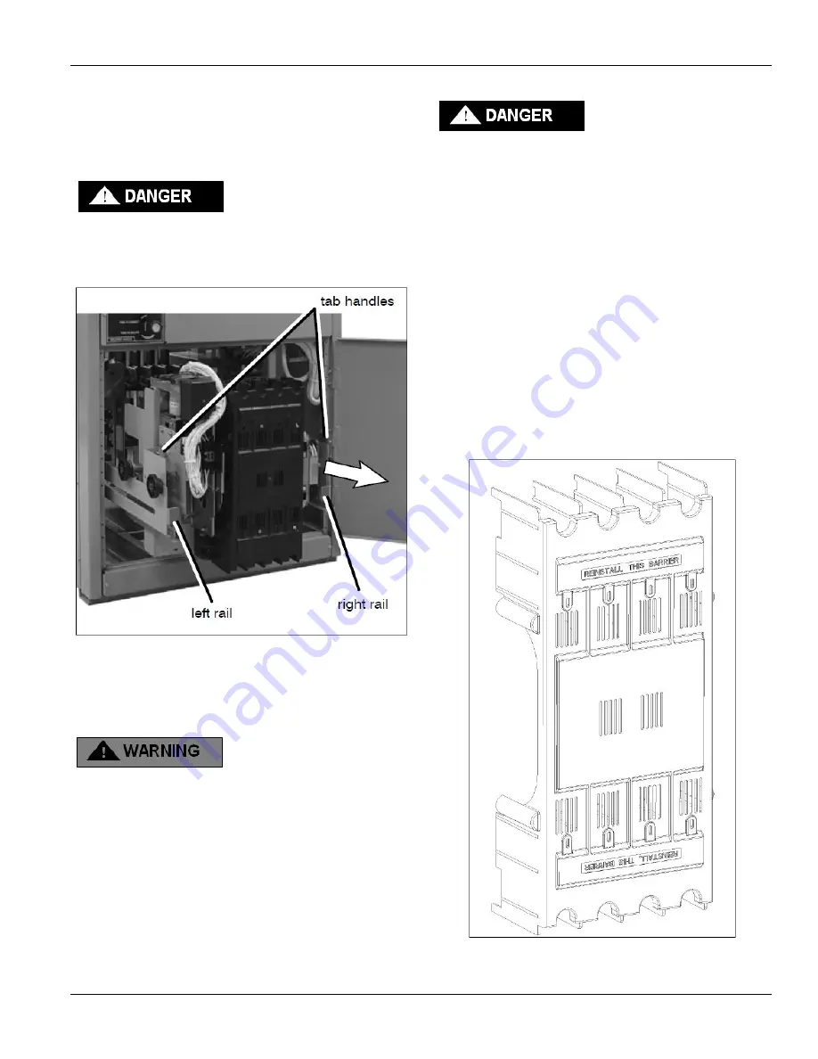
Open the lower enclosure door. Pull out both left and right
side rails then use the two tab handles to roll out the
transfer switch. It can be safely inspected in this position.
The transfer switch can also be removed for easier
maintenance operations. See Figure 17.
Hazardous voltage capable of causing shock,
burns, or death is used in this transfer switch.
Do not touch any control circuit terminals.
Figure 17. Transfer switch isolated
and pulled out for inspection
See page 16 for maintenance handle use. A lifting yoke
812053 is available to facilitate lifting by using an overhead
crane or similar equipment. See
WARNING
.
The Transfer Switch weighs about 120 lbs.
depending upon the number of poles. Use lifting
device 812053 or other device capable of lifting this
weight to avoid personal injury or equipment
damage. Two persons are recommended.
Contact Inspection
Contact condition should be checked annually. Discoloration
is normal. Do not file contacts. Instead use light emery paper
to clean up the contact surfaces. The non-replaceable main
contacts are designed to last the life of the transfer switch.
To prevent the possibility of fatal electrical shocks
and burns, bypass, isolate, and withdraw the
transfer switch before working on it.
1.
Deenergize transfer switch
(pages 7-11). Bypass, isolate,
and withdraw transfer switch. Use a voltmeter to verify
that no electrical power is present at the transfer switch
terminals.
2.
Use the maintenance handle
(page 16). Open the
contacts that will be inspected by using the detachable
maintenance handle.
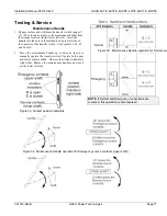
3.
Remove the barrier
(Figure 18). Use a Phillips (cross-
head) screwdriver to loosen (ccw) four or six round-head
screws that hold the barrier to the arc chutes. Then pull the
barrier straight outward to remove it.
4.
Reinstall the barrier
. After contacts are inspected and if
required, cleaned, install the barrier over the arc chutes.
Tighten (cw) the four or six screws to secure the barrier to
the arc chute insulator nuts.
Figure 18. Transfer switch barrier removal


