Maintenance & Repair Manual
SECTION 5
VIRTUOSO 5460P
50
110057
REV
K
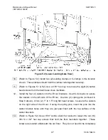
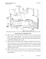
Figure 5.3 (Lower Landing Gate View)
6. (Refer to Figure 5.3) Tighten the ten (10) 3/8-16 x 3/4" hex cap screws which
fasten the floor members together. Take special care to align the scored lines on
the top of the smaller lift car floor members with the edges of the larger lift car floor
members before tightening these screws.
7. (Refer to Figure 5.3) Use two (2) 7/16" wrenches to reinstall the four (4) 1/4-20 x 1
hex cap screws, four (4) 1/4-20 nuts, and eight (8) washers into the front base
supports. Leave these screws and nuts very loose for now. The screws should be
installed so that the screw heads are toward the front of the lift and the lock
washers are under the nuts.
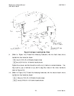
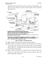
8. (Refer to Figure 5.4) Use a 3/16" hex key to turn the four (4) adjustment screws
(two (2) on each side) at the back of the lift car exactly three (3) full rotations
counterclockwise.


